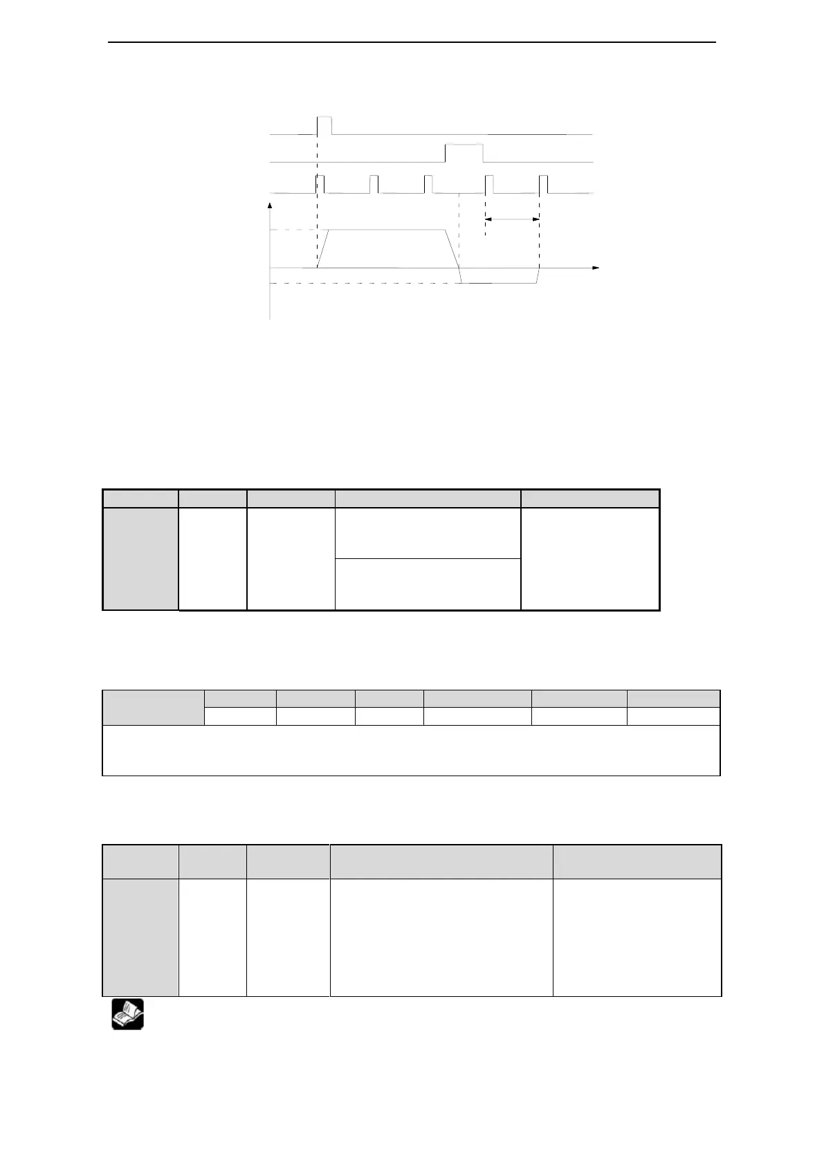
The timing diagram of finding reference origin of forward side:
Steps:
(1). Install limit switch at forward and reverse side. At the rising edge of /SPD-A, motor runs forward
at the speed of P4-01 to find the reference origin of forward side.
(2). After the working table hit the limit switch, the motor stop as the mode set by parameter P0-28
(3). Motor leaves the limit switch at the speed of P4-02. After the working table left the limit switch,
the motor run at the Z phase signal position of No.n optical encoder. This position is considered as the
coordinates origin, n is decided by parameter P4-00.
2. Define the reference origin
5-14-8. Set segment through communication
This parameter is set to certain segment, it will execute this segment. No need step change signal. This
parameter can be changed through communication.
For example: execute segment 2. Set F2-09=0, then set F2-09=02.
5-14-9. Motion start signal (/MRUN)
Default setting is no terminal
output. It is only valid in internal
position mode, similar to
positioning complete signal in
external pulse mode. It will output
when the motor is running, and will
not output when the motor stop.
Range 0000-0013, it can
be distributed to output
terminal by P5-50. When
it is set to 0001, means
output signal from SO1.
the terminal function cannot repeat. Please refer to chapter 5-12-3.
Mode 1,2,3,4: not distribute
to the terminal. To switch
the rotation direction.
Range: 0000-0014.
Distribute to input
terminal through
P5-27. When it set to
0001, it means input
signal from SI1.
Mode 5,6: not distribute to
the terminal. To define the
current point to origin.
 Loading...


