 Loading...
Do you have a question about the Xinje DS3 Series and is the answer not in the manual?
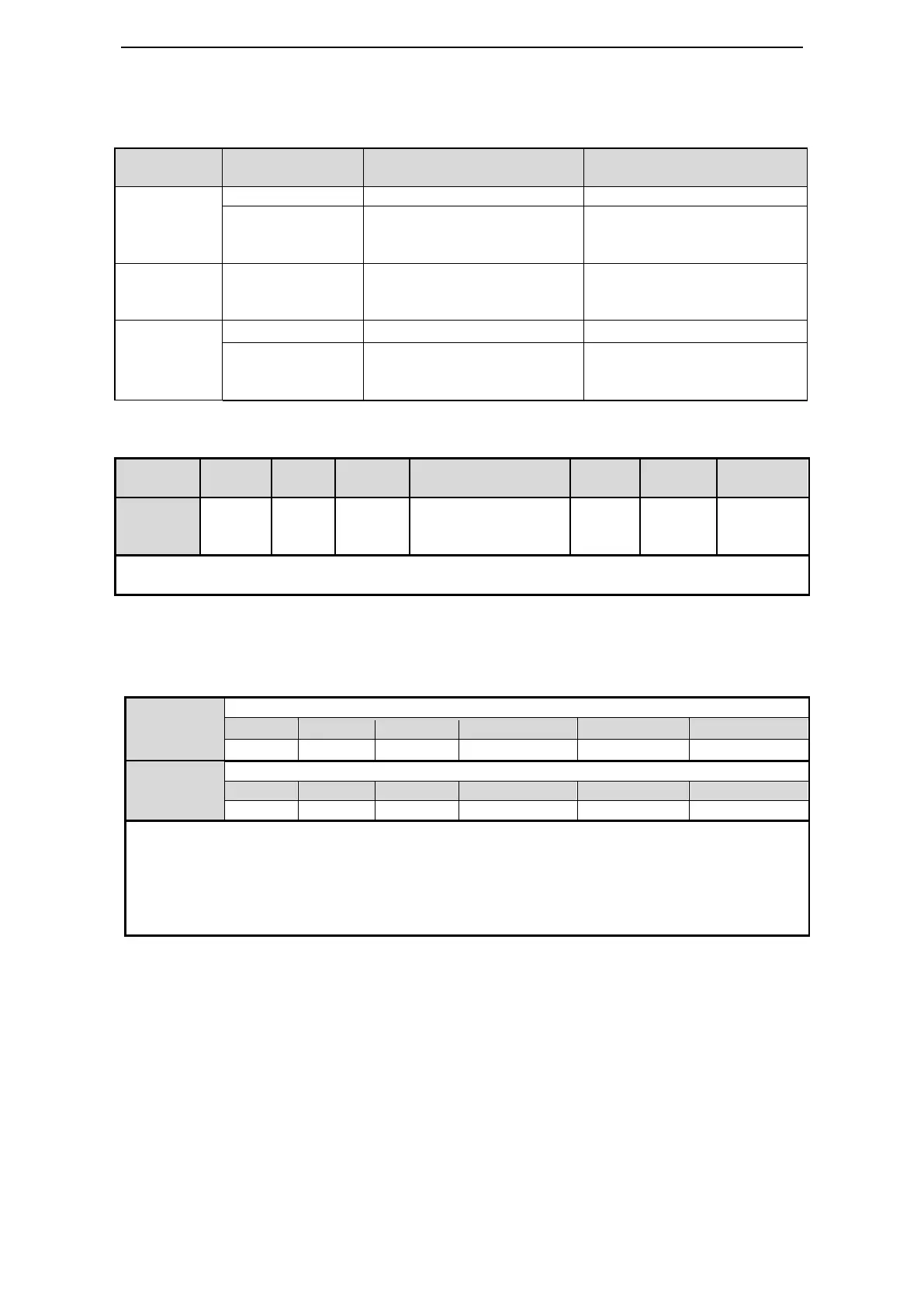
| Series | DS3 Series |
|---|---|
| Control Mode | Position, Speed, Torque |
| Power Supply | Single-phase/Three-phase |
| Output Power | 0.1kW to 7.5kW (depending on model) |
| Communication | CANopen |
| Encoder Type | Incremental/ Absolute |
| Protection Functions | Overcurrent, Overvoltage, Undervoltage, Overload, Overtemperature |
| Operating Temperature | 0°C to +55°C |
| Vibration Resistance | 5.9 m/s² (10-60 Hz) |
| Altitude | 1000m |
| Cooling Method | Forced air cooling |
| Humidity | 5% to 95% RH, non-condensing |
Guidelines for verifying delivered products.
Instructions and warnings for installing the servo drive.
Guidelines and warnings for electrical wiring procedures.
Checklist for verifying delivered products against order specifications.
Explains the naming convention and appearance of the servo drive models.
Explanation of the model naming convention for servo drives.
Describes the physical appearance and label details of the servo motor.
Explains the naming convention used for servo motors.
Instructions for proper installation of servo motors.
Recommended temperature range for storing servo motors.
Environmental conditions for optimal servo motor installation.
Guidelines for ensuring proper shaft alignment during installation.
Recommended conditions for storing servo drives.
Precautions for selecting an appropriate installation site for servo drives.
Table listing cable diameter requirements for different servo drive models.
Important warnings and precautions for wiring procedures.
Overview of the main circuit wiring for the DS3-PQA series.
Diagram showing terminal layout on the DS3-PQA servo drive.
Explanation and interface circuit for pulse input signals.
Wiring example for position control mode with DS3-21P5-PQA.
Overview of main circuit wiring for DS3E/DS3L-PFA series.
Terminal layout for DS3E/DS3L-PFA servo drives.
Explanation and interface circuit for pulse input signals.
Reference to wiring examples for position mode.
Overview of main circuit wiring for DS3-PTA series.
Terminal layout for DS3-PTA servo drives.
Detailed terminal information for DS3-PTA models.
Explanation and interface circuit for pulse input signals.
Reference to chapter for standard wiring examples for DS3-PTA.
Overview of basic operations and panel functions.
Description of the LEDs, buttons, and their functions on the operate panel.
How to switch between different operating modes using the panel.
Details bit contents and codes for speed/torque control status.
Functions for clearing alarms, resetting settings, and clearing offsets.
Table detailing control modes and their parameters.
List of basic function settings and their corresponding parameters.
Parameter for selecting external position mode.
Parameters for pulse command direction and form.
Parameter for selecting analog voltage speed control mode.
Parameters for setting the analog voltage corresponding to rated speed.
Setting for the zero clamp input signal.
Parameters for configuring the zero clamp mode.
Parameters for configuring the zero clamp mode.
Parameters for setting zero clamp speed.
Parameters for limiting the maximum output torque.
Function for limiting torque via input signal.
Function for limiting torque via analog voltage command.
Parameters for configuring soft start acceleration and deceleration times.
Parameter for selecting internal speed control mode.
Parameters for setting internal speeds 1, 2, and 3.
How to switch running speed using input signals.
Parameter for selecting pulse frequency speed command mode.
Reference to pulse command settings.
Parameter for setting pulse frequency at rated speed.
Parameter for selecting analog voltage torque control mode.
Parameters for setting analog voltage related to rated torque.
Parameters for limiting speed in torque control mode.
Parameters for limiting external speed in torque control mode.
Parameter for outputting signal when speed reaches limit.
Parameter for selecting internal torque control mode.
Parameter for setting internal torque command.
Table of fieldbus parameters for motion control.
Table of basic parameters for absolute encoder drives.
Details on encoder cables for absolute encoder systems.
Configuration of servo alarm and alarm reset signals.
Mapping of parameters to input terminals.
Basic parameters for DS3-PTA absolute encoder drives.
Parameter for selecting internal position mode.
Parameters for configuring internal position mode.
Explanation of different step modes for segment execution.
How to set segment numbers via communication.
Explanation of double edge triggering for segment changes.
Using signals to select position segments.
Parameters related to defining the reference origin.
Setting segments via communication.
Parameter for the motion start signal.
Parameters related to defining the reference origin.
Setting segments via communication.
Parameter for the motion start signal.
Guide to adjusting servo gain parameters for optimal performance.
Details on the two groups of gain parameters (Kp, Ki).
Parameters and modes for switching gain in position mode.
Detailed specifications for various servo motor models.
Tables of electrical and mechanical specs for servo motors.
Compares features of DS3E, DS3L, DS3-PTA, and DS2 servo drives.
Lists alarm codes, explanations, reasons, and solutions.
Table specifying regenerative resistor requirements for drives.
Details parameters P0-01, P0-02, P0-03, P0-05, P0-09, P0-10, P0-11, P0-12.
Lists control parameters P1-00 to P1-21.
Lists speed control parameters P3-00 to P3-13.
Lists reserved internal position parameters P4-00.
Lists P5 signal parameters.
Details U0-00 to U0-58 monitoring values.
Details U1-XX alarm and warning codes.
Maps parameters to Modbus addresses.
Steps for open-loop and jog testing without load.
Description of the welder equipment and its operation.
Compatibility table for incremental encoder servo systems.


