EasyManuals Logo
Home>Xinje>Servo Drives>DS3 Series

Xinje DS3 Series User Manual

Xinje DS3 Series
152 pages
To Next Page IconTo Next Page
To Previous Page IconTo Previous Page
Page #36 background imageLoading...
Page #36 background image
34
n.□xxx
Parity bit
2
02
0:no parity, 1: odd parity, 2: even
parity
Servo OFF
Note: data bit cannot be changed, it is 8 bits.
P7-02 RS485 communication protocol setting:
Parameter
Function
Default
setting
Range
Effective
time
P7-02
RS485 communication
protocol
1
1: Modbus Rtu protocol
2: Xnet fieldbus
Servo OFF
1. Support standard Modbus RTU protocol, it is used as Modbus slave device.
2. RS232 port and RS485 port can be used at the same time.
3-2-2Signal terminals
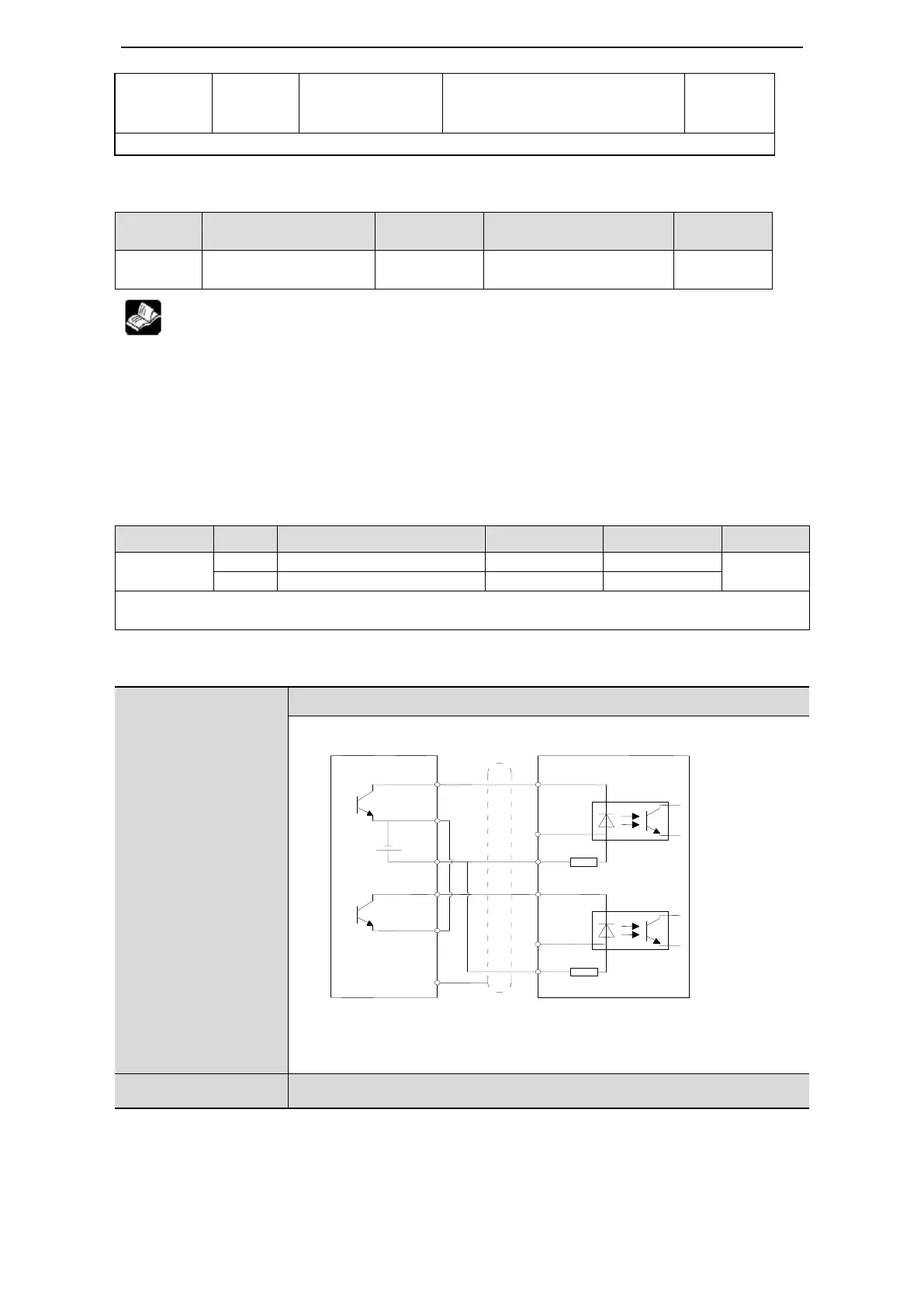
3-2-2-1. Pulse signal
Command
Choice
Meaning
P-input signal
D-input signal
Chapter
P0-10
xxx□
1
AB phase mode
A phase
B phase
5-3-2
2
Pulse + direction mode
Pulse
Direction
Collector open circuit (24V) input positive signal: P+24V/D+24V
Differential mode (5V) input positive signal: P+5V/D+5V
The interface circuit of Pulse + direction and CW, CCW, AB phase mode:
DS3E-2□P□-PFA
DS3E-4□P□-PFA
DS3L-2□P□-PFA
DS3L-4□P□-PFA
Open collector (24V)
PLC, SCM, etc servo drive
Note: (1) P+24V/P-, D+24V/D- power supply range is 18~25V. smaller
than 18V will cause pulse and direction error.
(2) Please use tisted shielded pair to avoid interference
DS3E-2□P□-PFA
Differential mode (5V)
COM0
Y0
+24V
P-
R=3.3K
COM1
Y1
D-
R=3.3K
P+5V
D+5V
Shield layer
0V
D+24V
P+24V
When upper
device is open
collector output,
please use this
wiring diagram.
Please note:
P+5V and
D+5V must be
vacant.

Table of Contents

Other manuals for Xinje DS3 Series

Questions and Answers:

Question and Answer IconNeed help?

Do you have a question about the Xinje DS3 Series and is the answer not in the manual?

Xinje DS3 Series Specifications

General IconGeneral
BrandXinje
ModelDS3 Series
CategoryServo Drives
LanguageEnglish

Related product manuals