XO 4 & XO FLEX TROUBLE SHOOTING GUIDE
Version 3.30 16
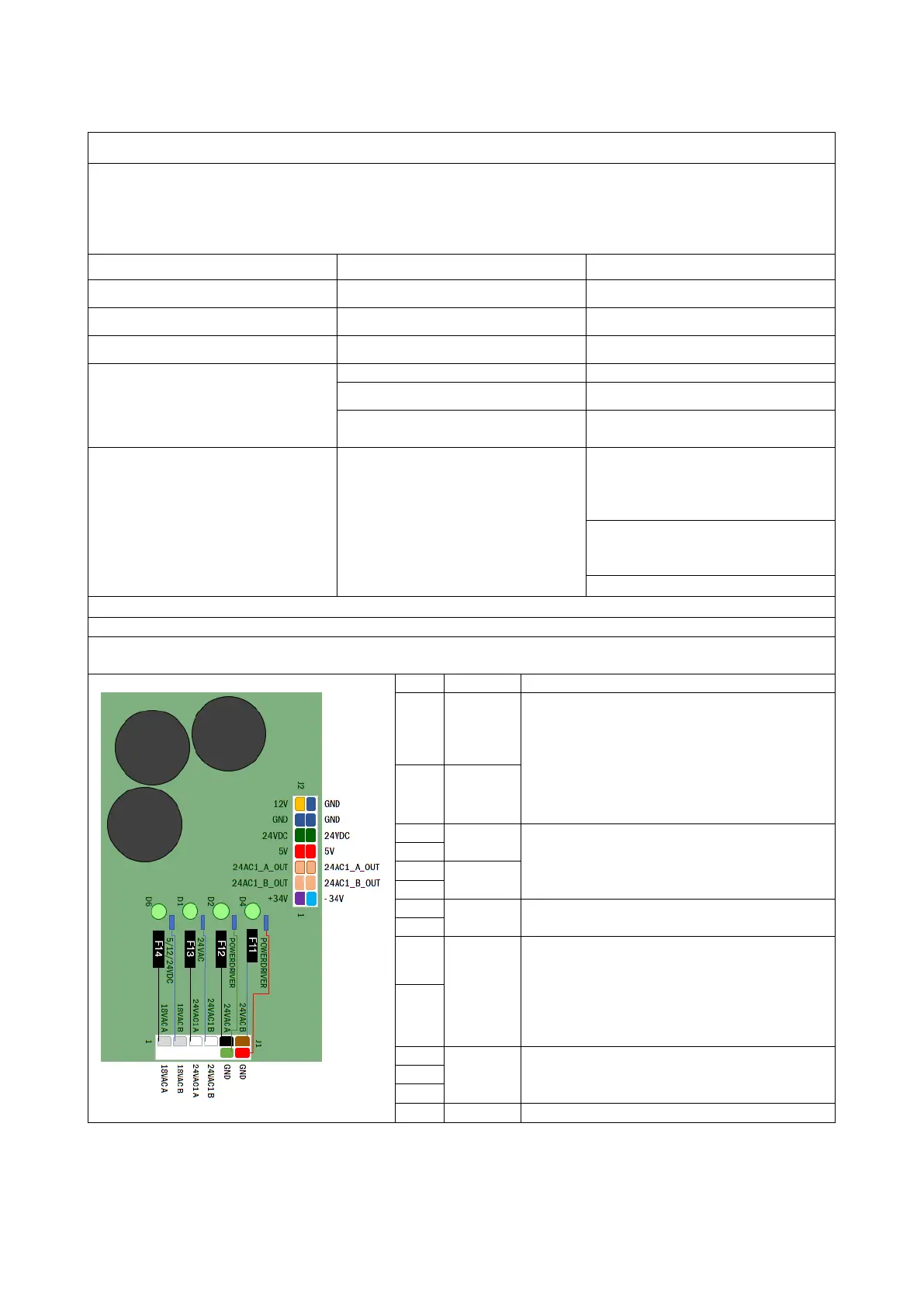
The “Power Supply PCB AN-371” transforms and manages the secondary voltages of the transformers
into precision voltages necessary for the operation of the unit. The secondary outputs are connected to
pin J1 and the precision voltage outputs are connected to pin J2.
Fuses F11 F12 F13 F14 protect the secondary outputs. LEDs D1, D2 D4 D6 indicate whether the
secondary output voltage is present. A set of fuses is available AN-305
Fault on 24VAC power supply.
Verify / Change fuse F13.
Fault on 24VAC power supply.
Verify / Change fuse F12.
Fault on 24VAC power supply.
Verify / Change fuse F11.
24VDC
Fault on 18VAC power supply.
Verify / Change fuse F14.
All fuses OK, no light in LED
Replace transformer MH-650
If one of the fuses blows after
replacement
Track the overload or short
circuit
supply PCB” are OFF and
LED’s on “Mains PCB” are
ON
Problem with the transformer
power supply.
Check that the transformer
connector is inserted properly
into J11 on the Mains PCB
board.
Check that transformer output
connector is inserted properly
into J1 on Power supply PCB
Precision voltage measurement:
On “J2” on “Power Supply AN-371” See picture and explanation down below
Concerning the mentioned precision voltage on “J1 Stand” on “Bridge PCB AN-368”, consult page 23
for picture and explanations.
1 +34V
LED D2 & D4 indicates ±34V is available.
±34V is transformed by the “power driver
AO-137” placed in the bridge Used for the
rotation of the micromotor MC3 and for
the functionality of the curing lamp. Check
the ±34V on the “J1 stand” located on the
“Bridge PCB AN-368”
8 -34V
24VAC
LED D1 indicates that 24VAC is available.
LED D800 located on the “Bridge AN-368”
indicates the presence of 24VAC.
24VAC
5VDC
Consult the 5V Surge Protection session
on page 17
5
24VDC
LED D6 indicates that 24 VDC is available.
LED D191 located on the “Bridge PCB
AN-368” indicates the presence of 24VDC.
The fuse F1 on the “Bridge PCB AN-368”
protects the 24VDC on the “
Bridge PCB
12
GND 0V
7 12V
 Loading...

