20
Scene Edit Buffers
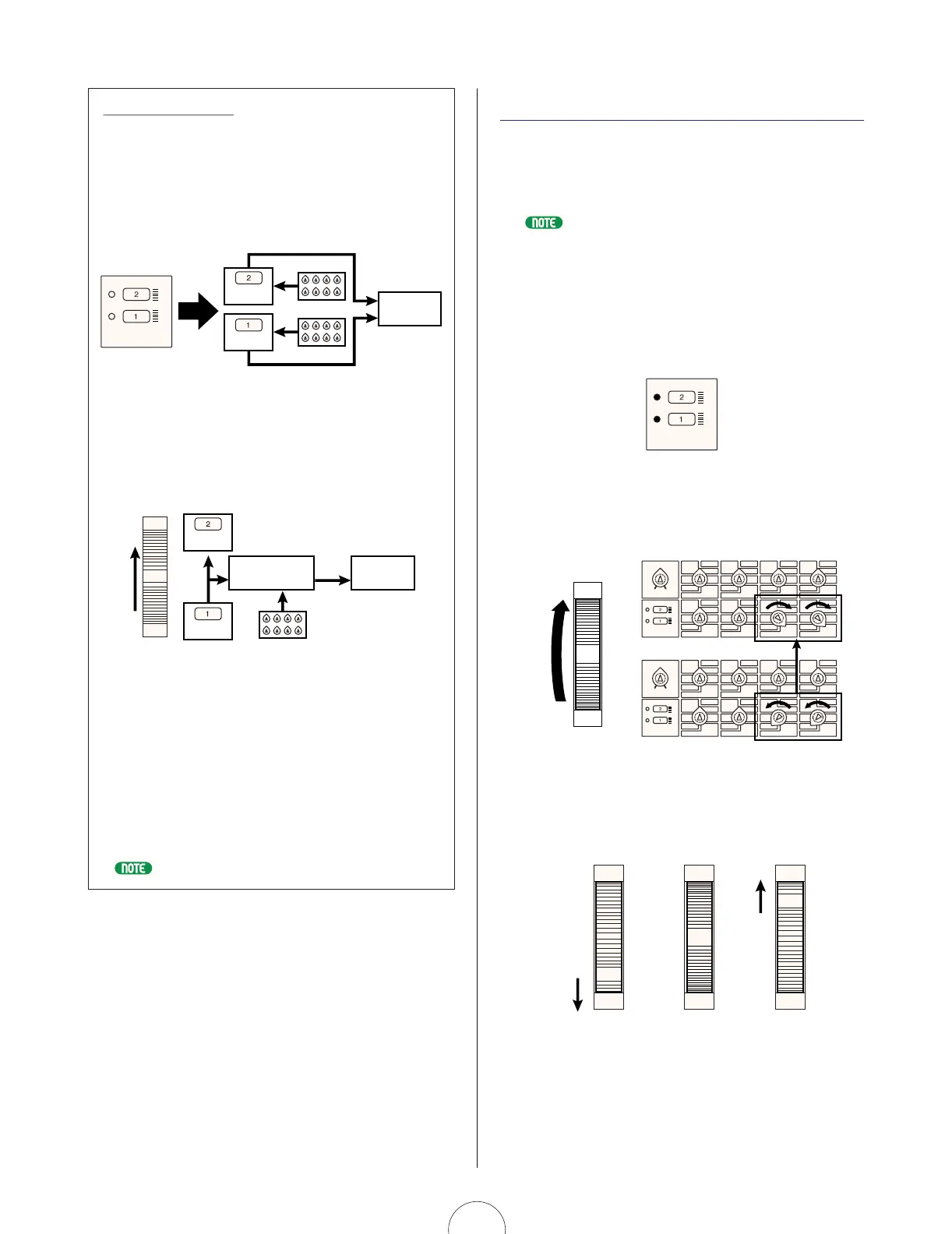
When you select a voice, the two Scenes are loaded into the
Scene edit buffers. Since each Scene has its own buffer, you
can “work” on each Scene separately. For example, if
[SCENE 1] is selected and you edit its parameters by turning
the knobs, this data will be maintained in Scene 1 even if
you select [SCENE 2] and start editing it. When you switch
back to Scene 1, it will recall your edited data (and not the
original Scene 1 data stored with the voice).
There’s also a Scene Control buffer, where parameter
changes by moving the [MODULATION] wheel (as well as
CONTROL knob positions when Scene Control is active) take
place. This sound can be stored in either Scene edit buffer at
any time using the Scene Store operation.
Since Scene editing, as well as Scene Store, Load and Swap
operations (see pages 21, 22), are taking place in the Scene
edit buffers, you need not worry about losing your original
Scene data as stored with the selected voice, unless you
perform a Voice Store operation to the same voice location.
However, since the Scene buffer is volatile, you will lose your
edited Scene data unless you perform a Voice Store
operation before selecting another voice.
For information about performing a Voice Store operation, see page 98.
Scene
Scene Control
Buffer
Tone
Generator
Scene
Control knobs
1-8
Scene Edit
Buffers
Tone
Generator
Scene
Scene
Control knobs
1-8
Scene Edit
Buffers
CTRL
SCENE
Scene Control
The Scene Control function lets you “morph”, or cross-fade
between the two Scenes by rolling the assignable
[MODULATION] wheel, or using an assignable Foot
Controller or any other continuous controller.
For information about assigning controllers, see page 95.
The procedure for activating the Scene Control function is
as follows:
1. Press both [SCENE] switches simultaneously.
The LEDs to the left of both switches will light
to indicate that Scene Control is active.
2. Roll the [MODULATION] wheel forward and
back (or use a Foot Controller, etc.) as you
play.
The minimum value of the [MODULATION] wheel (or Foot
Controller, etc.) plays Scene 1; the maximum value plays
Scene 2; any position between the two extremes (between
a range of 0 and 127) will play a blend of both Scenes
accordingly.
MODULATION
Scene 1 setting
Scene 1/2
equal balance
Minimum
Maximum
Halfway
MODULATION
Scene 2 setting
MODULATION
Scene 2 settings
Scene 1 settings
MODULATION
Scene 1
Scene 2
VOLUME
CTRL
SCENE
Algorithm
Wave
Attack
Attack
ASSIGN 1 ASSIGN 2
ASSIGN 3
ASSIGN 4
PEG Decay
Wave
VCO1
Fine
Fine
PEG Sw
FM Src2
LFO2 Spd
PmodDepth PmodDepth
Level
LFO1 Wave LFO1 Spd
LFO1 Dly
PW
ASSIGN 5
ASSIGN 6 ASSIGN 7 ASSIGN 8
VCF
Cutoff
Sync
Pmod Sw
Sync Pitch
Pitch Pitch
PEG Depth
Decay
Decay
VCO2
Level
FM Depth
FM Src1
Sync Pitch
Depth
Sustain
Ring
Mod
Sustain
Sync Pitch
Src
Edge
Port Time
Edge
Release
Release
Noise
Level
PW
HPF
Feedback
VCF
PWM Depth
PWM Src PWM Src
PWM Depth
Type
Reso
nance
Volume
FEG
Depth
Fmod
Depth
Amod Depth
Vel
Sens
Key
Track
Vel Sens
 Loading...