26
Using The
CONTROL Knobs
The eight CONTROL knobs give you direct access
to dozens of tone generator parameters that let
you coax literally an unlimited range of sounds
from the AN1x in real-time. They also let you
access and edit the individual events in each
step of the Step Sequencer (when the [EDIT
ROTARY] switch is set to the SEQ EDIT/SETUP
menu).
The CONTROL knobs are assignable, so you can
designate a specific parameter to be controlled by each
knob. You can use the Control Matrix to designate each
knob parameter for each Scene in each voice. Plus, you
can use the UTILITY SETUP menu Control function to
designate specific Control Change parameters to be
controlled by each knob when the [ASSIGN] switch is
selected, which not only is routed to the internal tone
generator, but is output via the MIDI [OUT] terminal, and
therefore can be used to simultaneously control an external
MIDI device.
When you turn a knob to edit a parameter, its parameter
name and value will automatically appear in the LCD, and
the knob data graph will track knob movements
accordingly. If you simply press a knob (push-switch)
without turning it, the parameter name and value will
appear in the LCD for visual confirmation, without
changing its value.
Turning a knob left decreases numeric values (or scrolls
toward the top of a list of available parameters), and
turning a knob right increases numeric values (or scrolls
toward the bottom of a list of available parameters).
For information about assigning controllers, see page 95.
ASSIGN 4
Sync Pitch
Src
Edge
Port Time
Edge
Release
Release
Noise
Level
Algorithm
Wave
Attack
Attack
ASSIGN 1 ASSIGN 2
ASSIGN 3
ASSIGN 4
PEG Decay
Wave
VCO1
Fine
Fine
PEG Sw
FM Src2
LFO2 Spd
PmodDepth PmodDepth
Level
LFO1 Wave LFO1 Spd
LFO1 Dly
PW
ASSIGN 5
ASSIGN 6 ASSIGN 7 ASSIGN 8
VCF
Cutoff
Sync
Pmod Sw
Sync Pitch
Pitch Pitch
PEG Depth
Decay
Decay
VCO2
Level
FM Depth
FM Src1
Sync Pitch
Depth
Sustain
Ring
Mod
Sustain
Sync Pitch
Src
Edge
Port Time
Edge
Release
Release
Noise
Level
PW
HPF
Feedback
VCF
PWM Depth
PWM Src PWM Src
PWM Depth
Type
Reso
nance
Volume
FEG
Depth
Fmod
Depth
Amod Depth
Vel
Sens
Key
Track
Vel Sens
If the [EDIT ROTARY] switch is set to positions 1 - 4 or
position 6, when you select a voice the [ASSIGN] switch
will automatically be selected (the LED beside it will light),
which means the group of parameters assigned to the
knobs by the UTILITY SETUP menu Control function can be
edited or controlled by turning the CONTROL knobs. To
access another group of knob parameters, simply press a
KNOB PARAMETER GROUP switch.
For more information about the knob parameters, see page 54.
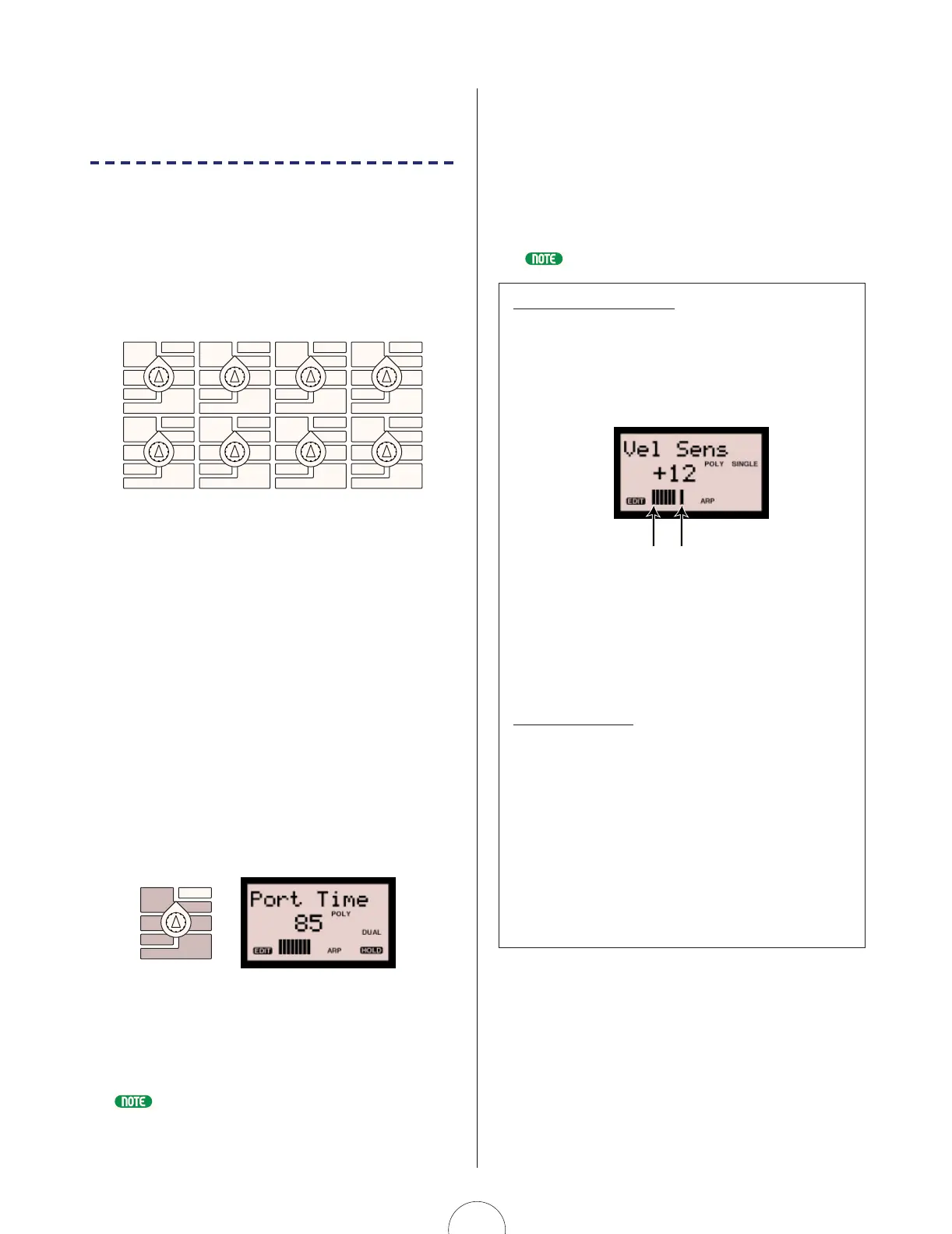
The Knob Data Graph
During tone generator or sequence event parameter editing,
a horizontal 11-segment “knob data graph” appears in the
lower area of the LCD. When you press a knob’s push-switch
for data confirmation (before turning the knob), the data
graph provides you with a visual reference of the parameter
value in relation to the current physical position of the knob.
A flashing segment in the data graph indicates the actual
value of the parameter, whereas shaded segments to the left
or right of the flashing segment indicate the current physical
position of the knob. As you turn the knob to the left or right,
the data graph will move left or right in accordance with the
knob movements.
Coarse/Fine Edit
You can edit CONTROL knob parameters in coarse or fine
increments and decrements, depending on how you turn the
knob. The knob data graph will display differently for each
method.
Simply turning a knob will increase or decrease the
parameter value in coarse (large) amounts. In this case, the
flashing indicator in the knob data graph will be canceled.
Turning a knob while pressing it will increase or decrease the
parameter value in fine (small) amounts. In this case, the
flashing indicator in the knob data graph will position as you
turn the knob, and will remain flashing when you release the
knob.
Actual value (flashing)Current knob position
 Loading...