MAINTENANCE, TROUBLESHOOTING & TECHNICAL SPECIFICATIONS 11 - 9
Signal Descriptions
The signal descriptions in Table 11-3 apply to the connector on the linear imager and are for reference only.
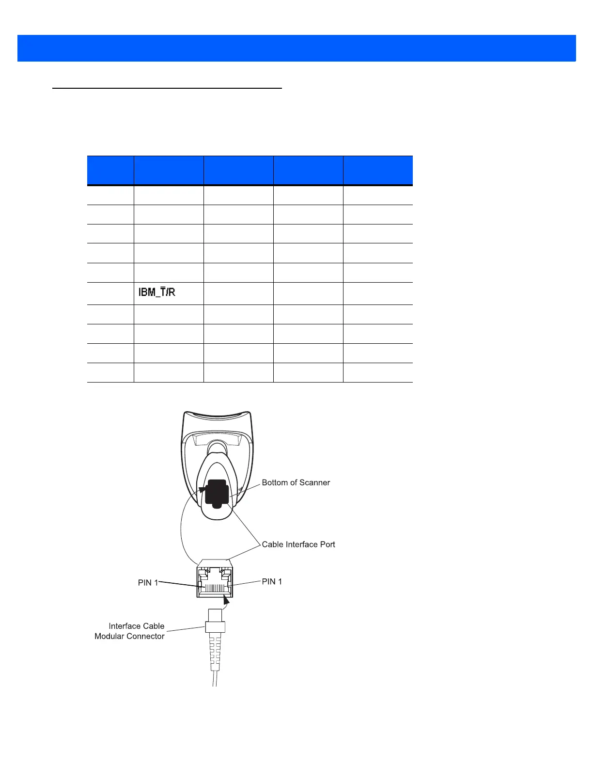
Figure 11-1
Scanner Cable Pinouts
Table 11-3
Signal Pin-outs
Pin IBM RS-232
Keyboard
Wedge
USB
1 Cable ID Cable ID Cable ID Cable ID
2 Power Power Power Power
3 Ground Ground Ground Ground
4 IBM_OUT TxD KeyClock Reserved
5 IBM_IN RxD TermData D +
6 RTS KeyData Reserved
7 Reserved CTS TermClock D -
8 Reserved Reserved Reserved Reserved
9 N/A N/A N/A N/A
10 N/A N/A N/A N/A
 Loading...