Layout
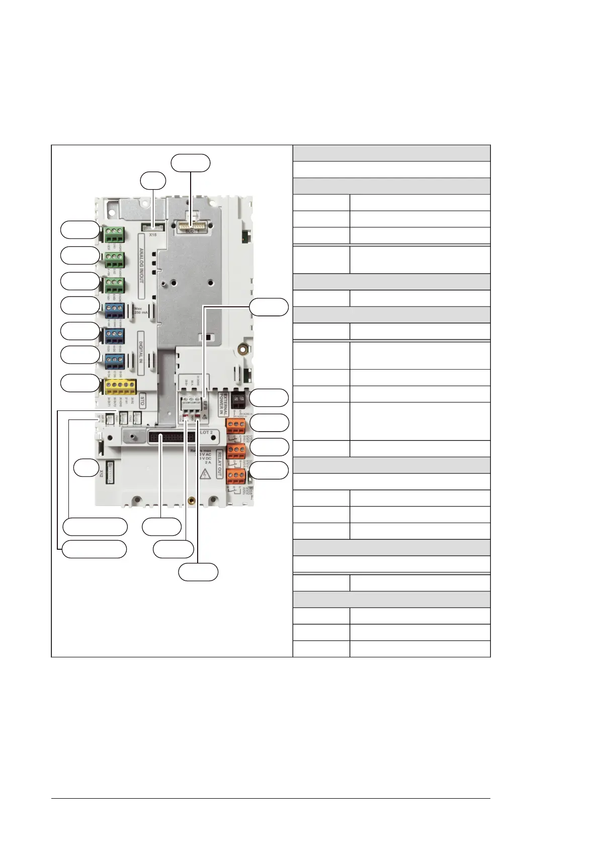
The layout of the external control connection terminals on the drive module control unit is
shown below.
SLOT 1
1…3
4…6
7…9
10…12
13…15
16…18
34…38
40, 41
19...21
22...24
25...27
X12
AIR IN TEMP
FAN 2, FAN 1
X15
SLOT 1
EFB
SLOT 2
BIAS
TERM
Option slot 1 (fieldbus adapter modules)
ANALOG IN/OUT
Analog input 11…3
Analog input 24…6
Analog outputs7…9
Auxiliary voltage output, digital in-
put common
10…12
DIGITAL IN
Digital inputs13…18
STO
Safe torque off connection.34…38
Internal air temperature NTC
sensor connection
AIR IN TEMP
Internal fan 2 connectionFAN2
Internal fan 1 connectionFAN1
Panel port (control panel connec-
tion, wired at the factory to the
control panel)
X12
Reserved to internal use.X15
EFB
EIA/RS-485 fieldbus connector
Bias resistor switchBIAS
End termination switchTERM
Connection terminals29…31
SLOT 2
Option slot 2 (I/O extension modules)
24 V AC/DC external power input40, 41
RO1 … RO3
Relay output 1 (RO1)19…21
Relay output 2 (RO2)22…24
Relay output 3 (RO3)25…27
112 Control unit