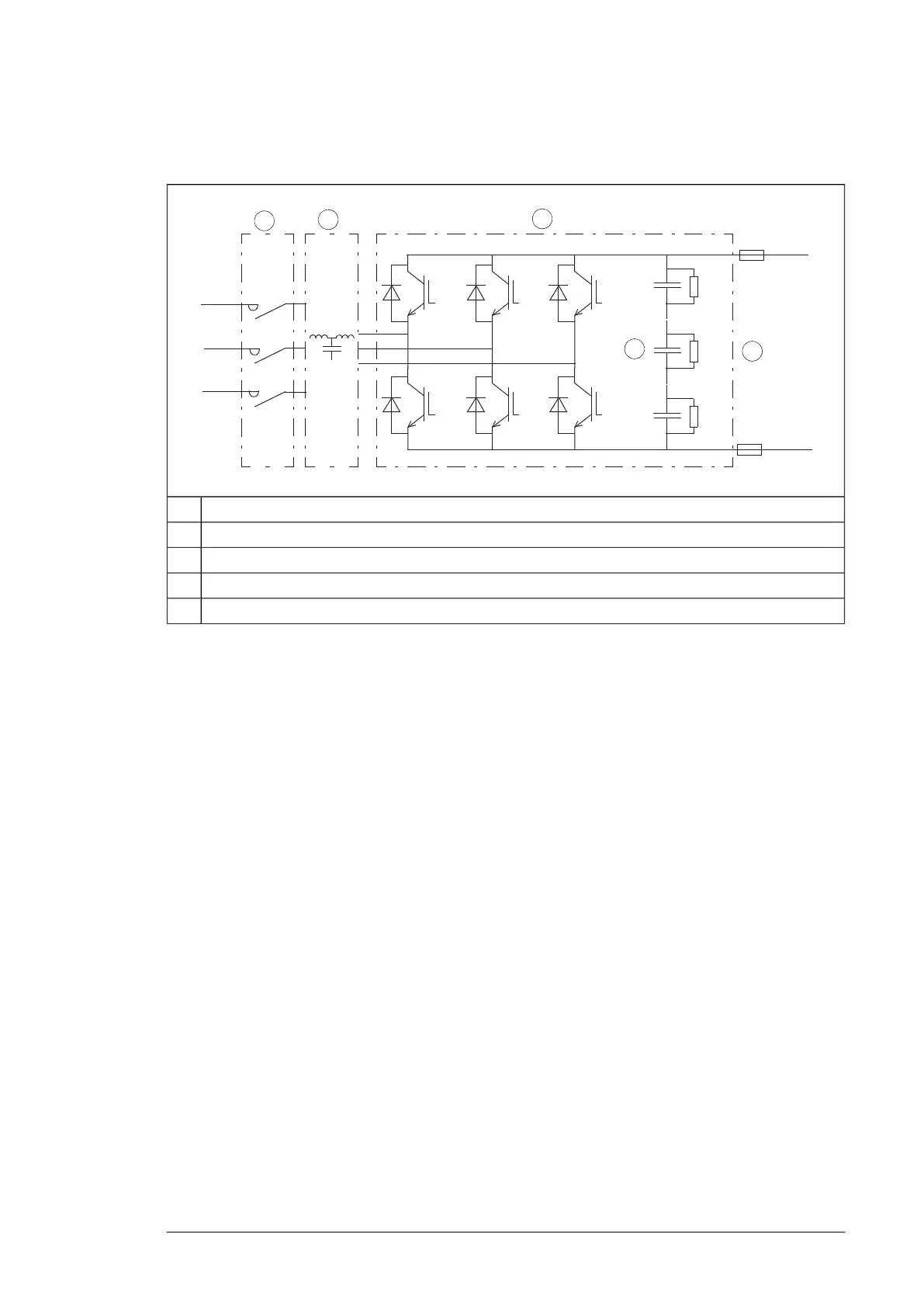
The following figure shows the simplified main circuit diagram of the line-side converter.
The line-side converter is controlled by a type ZCU control unit.
LCL filter contactor1
LCL filter2
Line-side converter3
DC capacitors4
DC link5
AC voltage and current waveforms
The AC current is sinusoidal at a unity power factor. The LCL filter suppresses the AC
voltage distortion and current harmonics. The high AC inductance smooths the line voltage
waveform distorted by the high-frequency switching of the converter. The capacitive
component of the filter effectively filters the high-frequency (over 1 kHz) harmonics.
Charging
Charging is needed to power up the DC link capacitors smoothly. Discharged capacitors
cannot be connected to the full supply voltage. The voltage must be increased gradually
until the capacitors are charged and ready for normal use. The drive contains a resistive
charging circuit consisting of fuses, contactor and charging resistors. The charging circuit
is in use after start-up until the DC voltage has risen to a predefined level.
■ Motor-side converter
The motor-side converter converts the DC back to AC that rotates the motor. It is also able
to feed the braking energy from a rotating motor back into the DC link. The motor-side
converter is controlled by a type CCU-24 control unit. This is called the drive control unit or
control unit in this manual.
Operation principle and hardware description 31
 Loading...