Unfasten the extraction/installation ramp and attach the LCL filter module to bottom plate.13
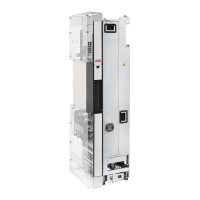
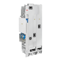
Drive module
Attach the extraction/installation ramp to the drive module pedestal guide plate.14
Remove the sheeting from the clear plastic shrouds (option +B051) of the drive module from both
sides.
15
Install the top metallic shroud to the drive module.16
Install the back shrouds to the drive module.17
To prevent the drive module from falling, attach its lifting lugs with chains to the enclosure frame.18
Push the drive module carefully into the enclosure along the extraction/installation ramp. Work
preferably with help from another person as shown above. Keep a constant pressure with one foot
on the base of the module to prevent the module from falling on its back.
19
Unfasten the extraction/installation ramp and attach the drive module to the bottom plate.20
LCL filter module and drive module attachments and intermediate electrical connections
Attach the LCL filter module and drive module to the punched section.21
Attach the LCL filter module to the side of drive module from top. Reinstall the cover.22
Attach the drive module and LCL filter module to the bottom plate.23
Connect the LCL filter busbars to the drive module busbars with the connecting busbars.24
Attach the LCL filter module to the drive module side from bottom.25
Connect the LCL filter fan power supply cable to connector FAN3:LCL.26
Air baffles
After the electrical installation has been done, install the air baffles. For instructions, see section
Installing the air baffles (page 137).
-
Connecting the motor cables and installing the shrouds
(option +B051)
See Connecting the motor cables and installing the shrouds (page 236)
Tasks (motor cables)Step
Install the grounding terminal to the drive module base.1
Run the motor cables to the enclosure. Ground the cable shields 360 degrees at the enclosure
entry.
2
Connect the twisted shields of the motor cables to the grounding terminal.3
Screw in and tighten the insulators to the drive module by hand. Install the T3/W2 connection ter-
minal to the insulators.
4
WARNING!
Do not use longer screws or bigger tightening torque than given in the installation
drawing. They can damage the insulator and cause dangerous voltage to be present
at the module frame.
Connect the phase T3/W2 conductors to the T3/W2 terminal.5
Install the T2/V2 connection terminal to the insulators. See the warning in step 4.6
Connect the phase T2/V2 conductors to the T2/V2 connection terminal.7
Install the T1/U2 connection terminal to the insulators. See the warning in step 4.8
Connect the phase T1/U2 conductors to the T1/U2 terminal.9
136 Installation example in Rittal VX25 enclosure
 Loading...