Remove the plastic sheeting from the motor cable clear plastic shroud (option +B051) from both
sides.
10
Install the shroud (option +B051) on the motor cable connections,11
Install the lower front cover to the drive module.12
Drill holes for the power cables to the bottom clear plastic shrouds.13
Remove the plastic sheeting from the bottom clear plastic shrouds.14
Install the bottom first shroud on the motor cable entry.15
Install the second shroud on the motor cable entry.16
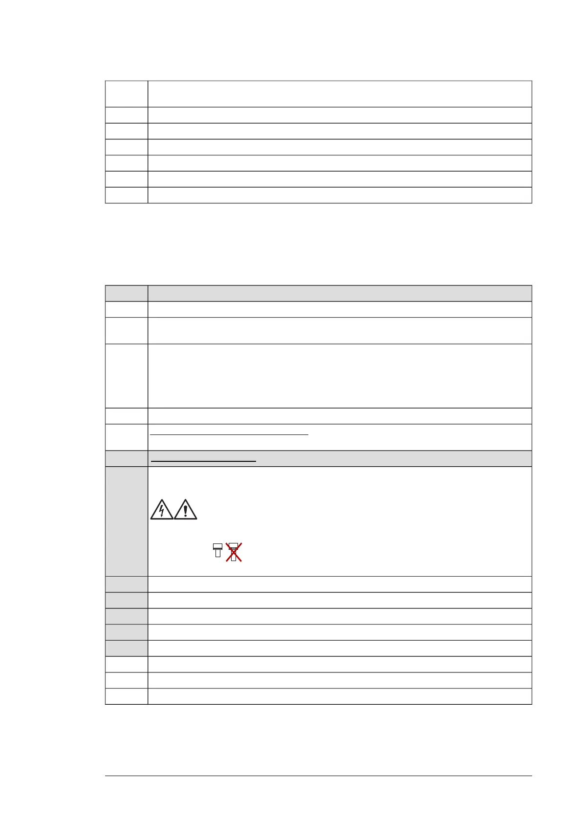
Connecting the input cables and installing the shrouds
(option +B051)
See Connecting the input power cables and installing the shrouds (page 239)
Tasks (input cables)Step
Ground the input cable shields (if present) 360 degrees at the enclosure entry.1
Connect the twisted shields of the input cables and separate ground cable (if present) to the enclosure
grounding busbar.
2
Step drill carefully sufficiently big holes to the entry clear plastic shroud for the cables to be connected.
Align the holes in the vertical direction according to the alignment holes in the shroud. Smooth the
hole edges.
3
Remove the plastic sheeting from both sides of the shroud.
Attach the cables firmly to the enclosure frame to prevent chafing against the hole edges.
Put the conductors of the input cables through the drilled holes in the clear plastic shroud.4
For drive modules without option +H370: Connect the input cable conductors to the drive module
L1/U1, L2/V1 and L3/W1 connection busbars, Go to step 12.
5
Tasks with option +H370: Do steps 6 to 11.
Screw in and tighten the insulators to the drive module by hand. Install the L1/U1 connection terminal
to the insulators.
6
WARNING!
Do not use longer screws or bigger tightening torque than given in the installation
drawing. They can damage the insulator and cause dangerous voltage to be present
at the module frame.
Connect the L1/U1 conductors to the L1/U1 connection terminal.7
Install the L2/V1 connection terminal to the insulators. See the warning in step 5.8
Connect the L2/V1 conductors to the L2/V1 connection terminal.9
Install the L3/W1 connection terminal to the insulators. See the warning in step 5.10
Connect the L3/W1 conductors to the L3/W1 connection terminal.11
Install the side clear plastic shroud and the upper front cover of the drive module.12
Install the entry clear plastic shroud (option +B051). and motor cable shroud (option +B051).13
Install the top clear plastic shroud (option +B051) to the drive module.14
Installing the air baffles
See:
Installation example in Rittal VX25 enclosure 137