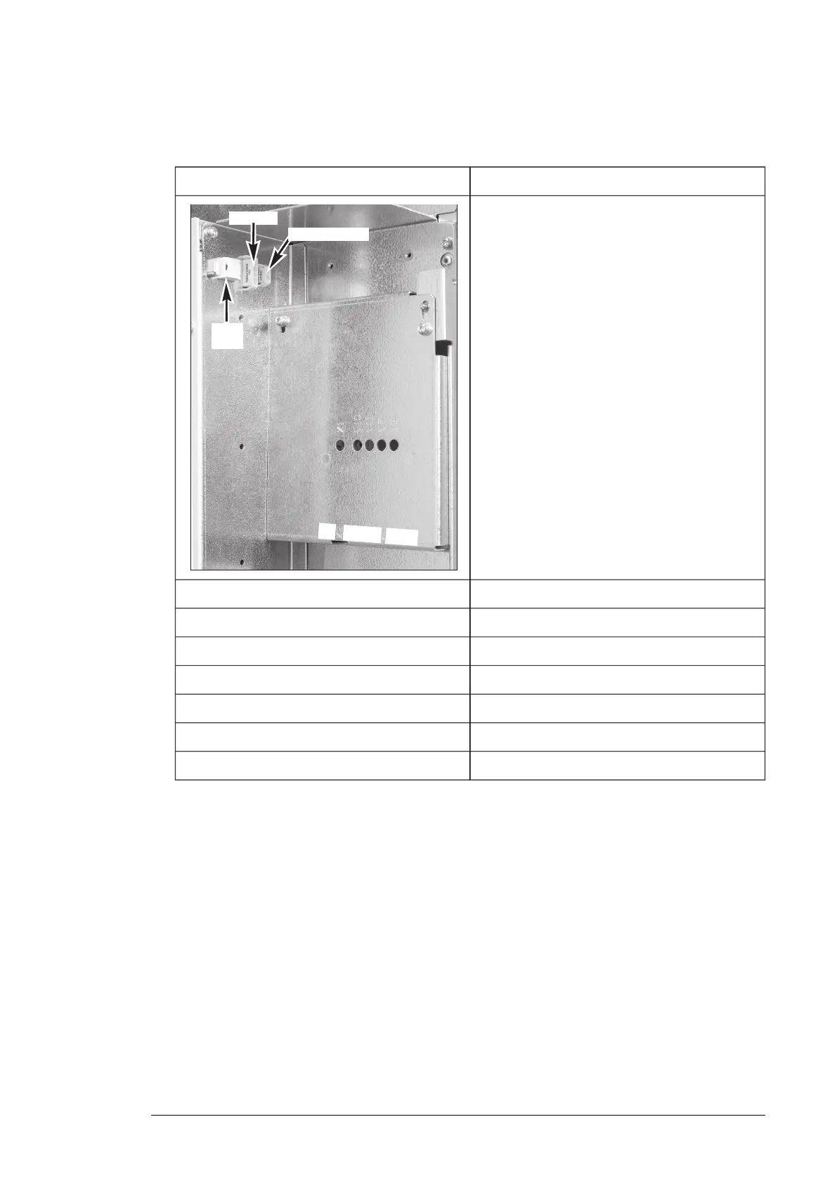
3. Connect the control cables to the drive module . Make sure that that cables are not
against sharp edges or bare live parts
ZBIBDrive module
QOIA ZBIB
X7 (STO1) X7 (STO1)
X8 STO2) X8 (STO2)
X2 X3
V2 V2
V7 V1
V8 V21
V13 V22
INU ZBIB
V1 V2
ISU ZBIB
V20 V21
2
1
V
8
V
1
3
V
2
V
7
INU STO
X
2
ISU ext. 24VDC
ISU
panel
X7 (STO1)INU STO
X8 (STO2)INU STO
X3X2
V2V2
V1V7
V20V8
V21V13
4. Connect the ground connection at the drive module end.
Maintenance
With the external control unit option +P906, the drive module removal procedure differs
slightly from the instructions given in chapter Maintenance: before you detach the drive
module, you must disconnect the control unit cables from the drive module in the following
way:
1. Remove the middle front cover of the drive module to be able to disconnect the cables.
2 × combi screws M4×8 T20, 2 N·m (18 lbf·in).
2. Disconnect the optical, 2 × STO, 24 V, and ground connections from the drive module,
and carefully remove the cables from the drive.
3. Wind the cables so they will not be damaged as the drive module is removed.
4.
Continue the drive module removal procedure as described in chapter Maintenance.
External control unit (option +P906) 131
 Loading...