Current [0(4)…20 mA, R
in
= 100 ohm] or voltage [0(2)…10 V, R
in
>200 kohm]. Change of setting requires
changing the corresponding parameter.
1)
Total load capacity of the Auxiliary voltage output +24V (X2:10) is 6.0 W (250 mA / 24 V) minus the power
taken by the option modules installed on the board.
2)
In scalar control: See Menu > Primary settings > Start, stop, reference > Constant speeds / constant
frequencies or parameter group 28 Frequency reference chain.
3)
In vector control: See Menu > Primary settings > Start, stop, reference > Constant speeds / constant
frequencies or parameter group 22 Speed reference selection.
Connected with jumpers at the factory.4)
Use shielded twisted-pair cables for digital signals.5)
Ground the outer shield of the cables 360 degrees at the cabinet entry.6)
WARNING! Connect external AC power supply (24 V AC) to control unit connectors 40 and 41.
If you connect it to connector AGND, DGND or SGND, the power supply or the control unit can
get damaged.
7)
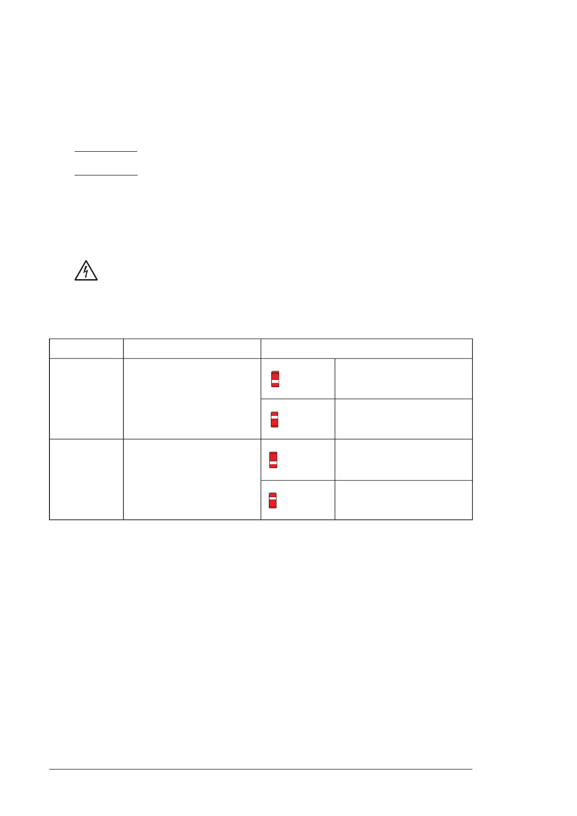
■ Switches
PositionDescriptionSwitch
Bus not terminated (default)
EFB link termination. Must be set
to the terminated (ON) position
when the drive (or another device)
is the first or last unit on the link.
TERM
S4
Bus terminated
Bias off (default)
Switches on the biasing voltages
to the bus. One (and only one)
device, preferably at the end of the
bus must have the bias on.
BIAS
S5
Bias on
Additional information on I/O connections
■ PNP configuration for digital inputs (X2 & X3)
Internal and external +24 V power supply connections for PNP configuration are shown in
the figure below.
114 Control unit
 Loading...