■ Corner-grounded and midpoint-grounded delta systems
WARNING! Do not install the drive on a corner-grounded or midpoint-grounded
delta system. Disconnecting the EMC filter and ground-to-phase varistor does not
prevent damage to the drive.
■ Identifying the grounding system of the electrical power network
WARNING!
Only a qualified electrical professional may do the work instructed in this section.
Depending on the installation site, the work may even be categorized as live
working. Continue only if you are an electrical professional certified for the work.
Obey the local regulations. If you ignore them, injury or death can occur.
To identify the grounding system, examine the supply transformer connection. See the
applicable electrical diagrams of the building. If that is not possible, measure these voltages
at the distribution board, and use the table to define the grounding system type.
1. input voltage line to line (U
L-L
)
2. input voltage line 1 to ground (U
L1-G
)
3. input voltage line 2 to ground (U
L2-G
)
4. input voltage line 3 to ground (U
L3-G
).
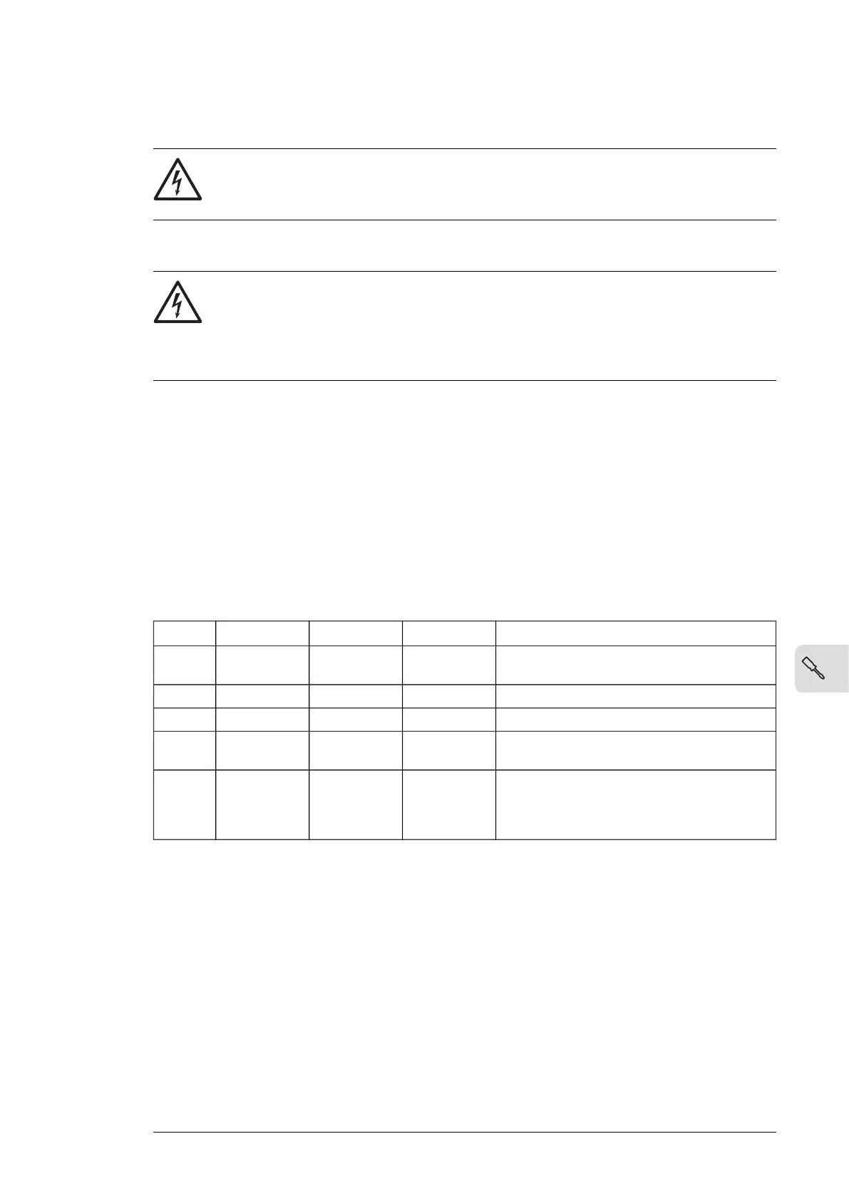
The table below shows the line-to-ground voltages in relation to the line-to-line voltage for
each grounding system.
Electrical power system typeU
L3-G
U
L2-G
U
L1-G
U
L-L
Symmetrically grounded TN system (TN-S sys-
tem)
0.58·X0.58·X0.58·XX
Corner-grounded delta system (nonsymmetrical)01.0·X1.0·XX
Midpoint-grounded delta system (nonsymmetrical)0.5·X0.5·X0.866·XX
IT systems (ungrounded or high-resistance-
grounded [>30 ohms]) nonsymmetrical
Varying level
versus time
Varying level
versus time
Varying level
versus time
X
TT system (the protective earth connection for
the consumer is provided by a local earth elec-
trode, and there is another independently installed
at the generator)
Varying level
versus time
Varying level
versus time
Varying level
versus time
X
Electrical installation 97
 Loading...