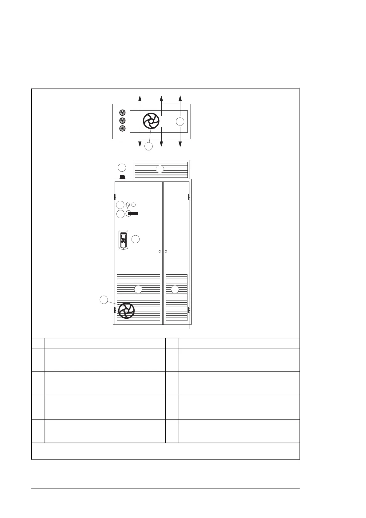
Layout example, door closed
This diagram shows a cabinet layout example with the input power cable entry from top and
the motor cable entry from bottom.
Operating handle of the disconnector6Air inlet for the drive module1
Rubber grommets for degree of protection7An extra fan is not necessary if an extra air baffle
is used on the cabinet roof (see the following
layout examples)
2
Roof air flow viewed from top8Air outlet for the drive module and LCL filter
module and other equipment on the cabinet roof.
An exhaust fan if needed.
3
Fan required for IP20, IP42 or IP54 air outlet kit,
has to be ordered separately. See Cooling
fans (page 163).
9Drive control panel with DPMP-01 mounting plat-
form. The control panel is connected to the drive
module control unit inside the cabinet.
4
-Contactor control switch and emergency stop
switch (connected to the contactor control circuit
inside the cabinet)
5
Note: The sizes of the air inlet and outlet gratings are critical for proper cooling of the drive module. For losses
and cooling data requirements, see the technical data.
52 Guidelines for planning the mechanical installation
 Loading...