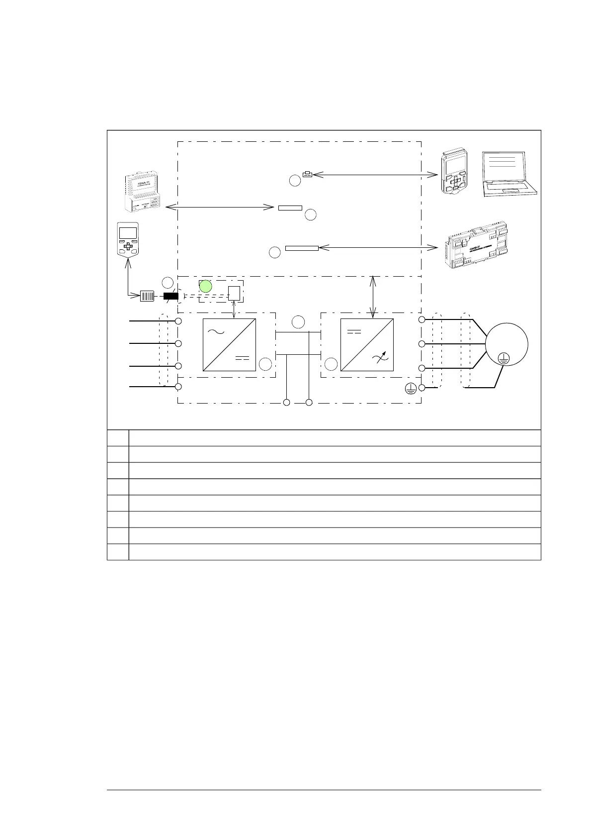
Overview of power and control connections
The diagram shows the power connections and control interfaces of the drive module.
L1
L2
L3
PE
U2
V2
W2
M 3 ~
L1
L2
L3
PE
4 6
5
ACQ580-34
UDC- UDC+
Slot 2
Slot 1
1
2
..........
..........
..........
..........
..........
..........
Panel port
3
A
7
Line-side converter control unitA
Option slot 1 for optional fieldbus adapter modules1
Option slot 2 for optional I/O extension modules2
Panel port3
Line-side converter4
DC link5
Motor-side converter6
Socket for external control panel (not required for normal operation of the drive)7
Type designation label
The type designation label includes a rating, markings, a type designation and a serial
number, which allow individual recognition of each drive module. The type designation label
is located on the front cover. An example label is shown below.
Operation principle and hardware description 37
 Loading...