EasyManuals Logo

ABB ACS380 Series User Manual

ABB ACS380 Series
462 pages
To Next Page IconTo Next Page
To Previous Page IconTo Previous Page
Page #439 background imageLoading...
Page #439 background image
Fieldbus control through a fieldbus adapter 439
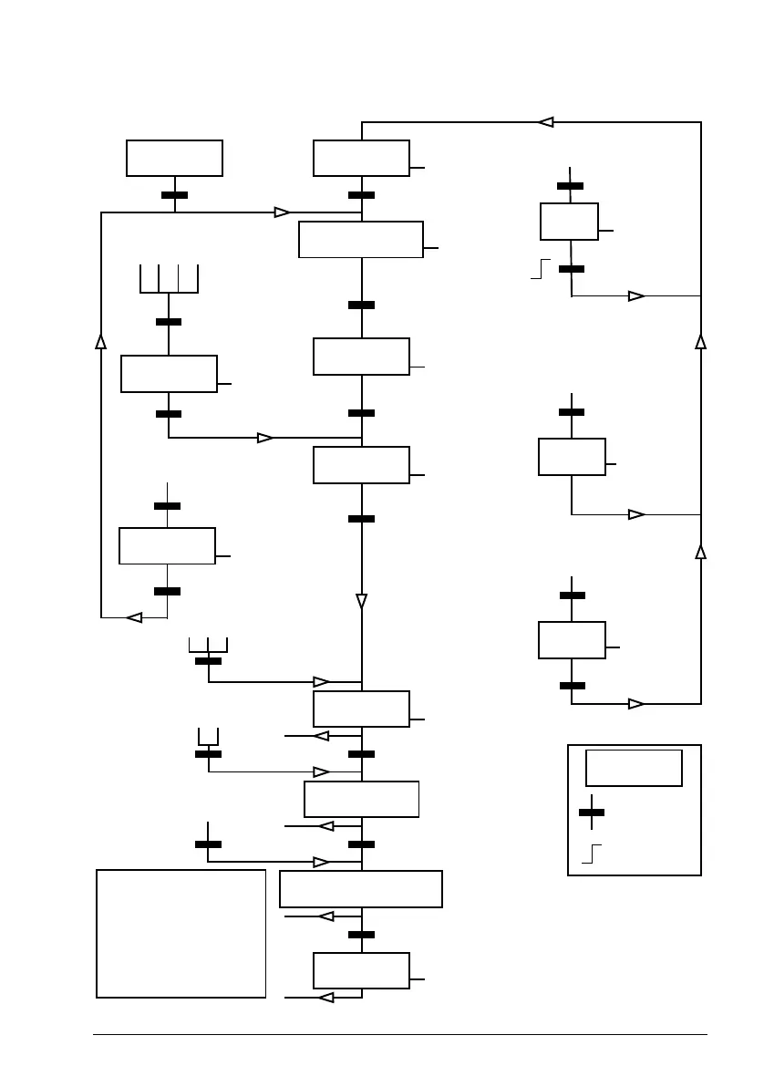
The state diagram (valid for ABB drives profile only)
ABCD
CD
B
BCD
D
A
C
D
SWITCH-ON
INHIBITED
NOT READY TO
SWITCH ON
READY TO
SWITCH ON
READY TO
OPERATE
OPERATION
INHIBITED
OFF1
ACTIVE
OPERATION
ENABLED
RFG: OUTPUT
ENABLED
RFG: ACCELERATOR
ENABLED
OPERATION
OFF2
ACTIVE
FAULT
OFF3
ACTIVE
MAINS OFF
SW b6=1
SW b0=0
CW b0=0
CW=xxxx x1xx xxxx x110
SW b0=1
SW b1=1
CW=xxxx x1xx xxxx 1111
CW=xxxx x1xx xxxx x111
CW = Control word
SW = Status word
bx = bit x
n= Speed
I = Input Current
RFG = Ramp Function
Generator
f = Frequency
SW b2=0
from any state
Fault
from any state
from any state
SW b1=0
n(f) = 0 / I = 0
SW b5=0
Emergency stop
OFF3 (CW b2=0)
SW b2=1
CW=xxxx x1xx xxx1 1111
CW=xxxx x1xx xx11 1111
CW b4=0
CW b5=0
CW b6=0
OFF1 (CW b0=0)
from any state
CW b3=0
n(f) = 0 / I = 0
STATE
condition
rising edge of
bit
operation
inhibited
Power ON
SW b3=1
CW b7=1
Emergency stop
OFF2 (CW b1=0)
SW b4=0
SW b8=1
CW=xxxx x1xx x111 1111

Table of Contents

Other manuals for ABB ACS380 Series

Questions and Answers:

Question and Answer IconNeed help?

Do you have a question about the ABB ACS380 Series and is the answer not in the manual?

ABB ACS380 Series Specifications

General IconGeneral
BrandABB
ModelACS380 Series
CategoryDC Drives
LanguageEnglish

Related product manuals