Program features 75
Example 2: If the reference switching frequency is set to 12 kHz and the minimum
switching frequency is set to 1.5 kHz (or 1 kHz), the drive maintains the highest
possible switching frequency to reduce motor noise and only when the drive heats it
will decrease the switching frequency. This is useful, for example, in applications
where low noise is necessary but higher noise can be tolerated when the full output
current is needed.
Parameters
Parameter: 97.01 Switching frequency reference and 97.02 Minimum switching
frequency.
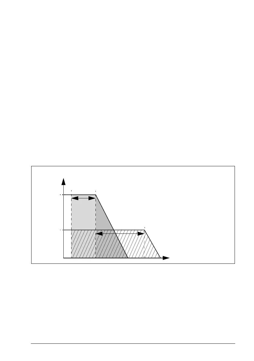
Speed compensated stop
Speed compensation stop is available for example for applications where a conveyer
needs to travel a certain distance after receiving the stop command. At maximum
speed, the motor is stopped normally along the defined deceleration ramp, after the
application of a user defined delay to adjust the distance traveled. Below maximum
speed, stop is delayed still more by running the drive at current speed before the
motor is ramped to a stop. As shown in the figure, the distance traveled after the stop
command is the same in both cases, that is, area A + area B equals area C.
Speed compensation does not take into account shape times (parameters 23.32
Shape time 1 and 23.33 Shape time 2). Positive shape times lengthen the distance
traveled.
Speed compensation can be restricted to forward or reverse rotating direction.
Speed compensation is supported in both vector and scalar motor control.
Parameters
Parameters: 21.30 Speed compensated stop mode, 21.31 Speed compensated stop
delay and 21.32 Speed comp stop threshold.
Used
speed
A
Motor speed
Max.
speed
B
C
t (s)
Area A + Area B = Area C
Stop
command
D1
D1 = Delay defined by parameter
21.31
D2 = Additional delay calculated by
speed compensated stop
D2

 Loading...


