DCS500 Pin and Parameter list
A 4
General
The entire software is made up of connected function blocks. Each of these individual function
blocks constitutes a subfunction of the overall functionality.
The function blocks can be subdivided into two categories:
• Function blocks which are permanently active, are almost always in use; these are
described on the following pages.
• Function blocks which, although they are available within the software as standard
features, have to be expressly activated when they are needed for special requirements.
These include, for example: AND gates with 2 or 4 inputs, OR gates with 2 or 4 inputs,
adders with 2 or 4 inputs, multipliers/dividers, etc. or closed-control-loop functions, such
as integrator, PI controller, D-T1 element, etc.
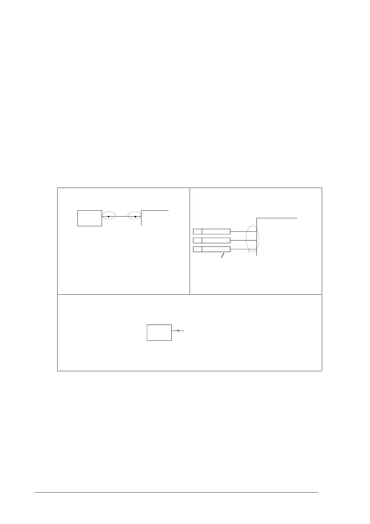
All function blocks are characterized by input and output lines, equipped with numbers. These
inputs/outputs can likewise be subdivided into two categories:
Inputs for designating connections
901
DRIVE LOGIC
DI7
10713
Output Input
When you want to alter connections between
function blocks, proceed as follows:
• first select the input
• and then connect to output.
All those connections possessing one dot
each at their beginning and end can be
altered.
Parameters for setting values
(such as ramp-up time / ramp-down time,
controller gain, reference values and others)
RAMP GENERATOR
P6
P2
P4
1708
1709
1710
Parameter
Val ue
Val ue
Val ue
Default setting
For input / parameter selection, the following applies:
• Ignore the two right-hand digits; the remaining digits are the group and to be selected
• The two right-hand digits are the element and to be selected
DI7
10713
The selection can be done with the control panel CDP312, using the (double-up-down) for the
group and the (single-up-down) for the element or a PC-based tool program CMT/DCS500B.
Group 107
element 13

 Loading...


