Functional Software description
6 DCS 500 Software Description
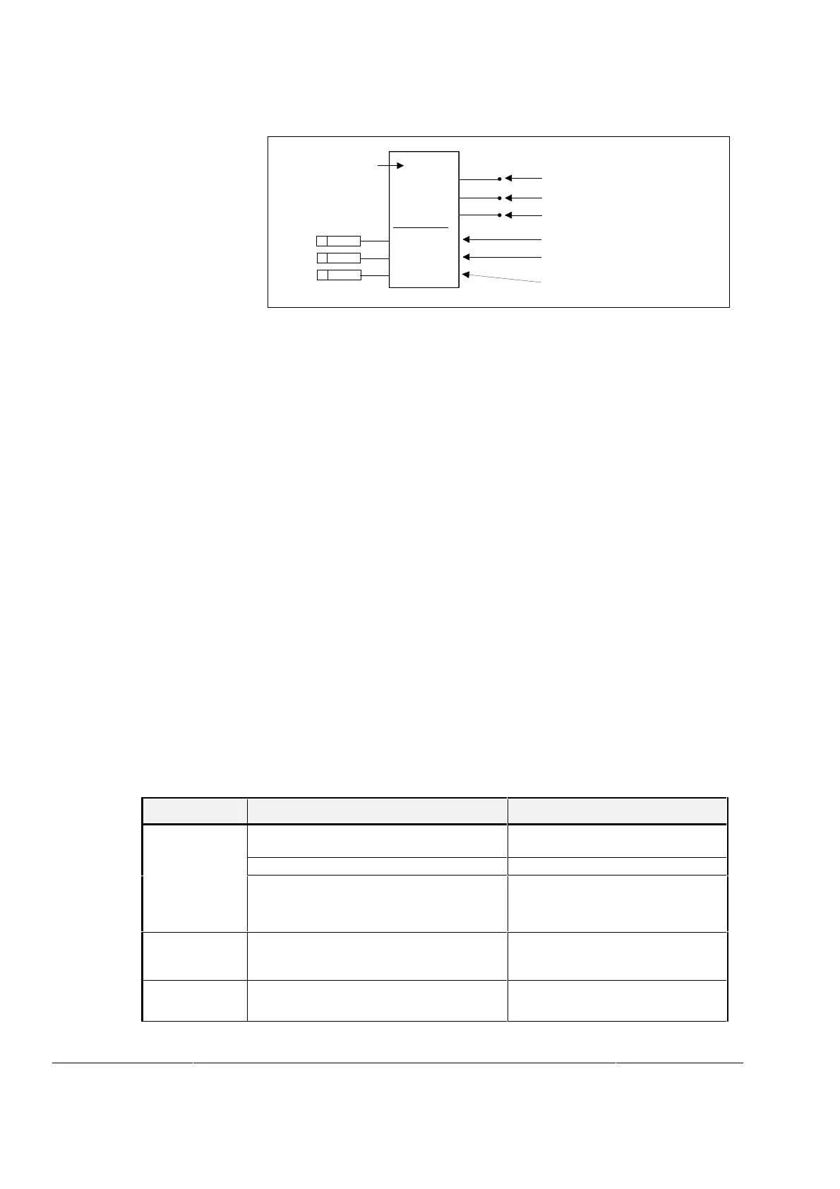
Analog Inputs
OUT+
AI2
107
OUT-
ERR
CONV MODE
HIGH VALUE
LOW VALUE
108
109
10707
10708
10709
ST5
SP
Value that corresponds to maximum
input (+10V or +20mA)
Value that corresponds to
minimum input (-10V or -20mA)
Output value
Negated output value
Error code
Selection of the Input signal type
Function Block name
P1
P3
P2
20000
-20000
1
Figure 8 Analog Input Function Block
Maximum number of analog inputs is seven. The first five chan-
nels, AITAC, AI1, AI2, AI3 and AI4, are available with the SDCS-
CON-2 or SDCS-IOB-3 boards. The last two channels, AI5 and
AI6, are connected by means of the SDCS-IOE-1 extension I/O
board.
Analog inputs are scaled with parameters:
HIGH VALUE (1XX) = value in OUT+ (XXXXX) that corresponds to
maximum input value (normally +10V or +20 mA).
and
LOW VALUE (1XX) = value in OUT+ (XXXXX) that corresponds to
minimum input value (normally -10V or +20 mA).
If offset balancing is needed, the value of the HIGH and LOW
VALUE has to be increased or decreased slightly.
Note. The temperature measurements are scaled internally in AI2
and AI3 (Ω or °C). The parameters HIGH VALUE and LOW VALUE
have no significance in that case.
Signal Type Selection for In-
puts
The input signal type is defined by parameter CONV MODE (1XX).
The following table shows all possible values for analog input sig-
nals in the DCS500B software.
Analog Input
AIx CONV MODE-parameter selection Terminal boards & settings:
AITAC
1 = -10...+10V
-20...+20mA
IOB-3: ----
IOB-3: S1:1-2 connected
2 = 4...20mA, unipolar IOB-3: S1:1-2 connected
3 = Tacho generator voltage
- 10V...+10V
CON-2: 3:1-4: 90-270V
X3:2-4: 30-90V
X3:3-4: 0-30V
AI1
1 = -10...+10V
-20...+20mA
CON-2; IOB-3: ----
CON-2: 500Ω connected X3:5-6
IOB-3: S1:3-4 connected
2 = 4...20mA, unipolar CON-2: 500Ω connected X3:5-6
IOB-3: S1:3-4 connected