30 Electrical installation
Connecting the module to the DeviceNet network
Connect the bus cable to terminal block X1 on the adapter module.
Terminal block description
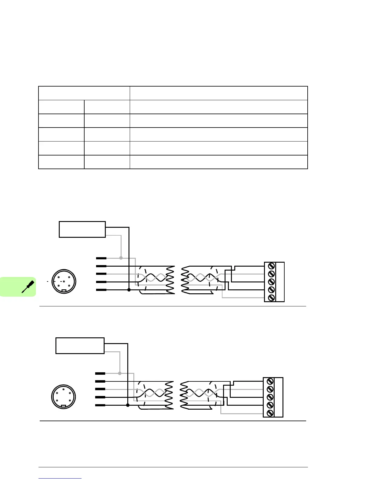
Connection examples
5-pin micro-style connector:
5-pin mini-style connector:
X1 Description
1 V- Network power supply ground (0V DC)
2 CAN_L CAN_L bus line
3 SHLD Network cable shield
4 CAN_H CAN_H bus line
5 V+ Network power supply source (24V DC)
5
3
Male micro-style
SHLD
CAN_L
CAN_H
V-
1234
connector
4
1
2
X1
0 V
+24 V
Network
power supply
4
5
3
1
2
FDNA
5
V+
V+
3
2
Male mini-style
4
5
3
1
2
connector
4
51
0 V
+24 V
Network
power supply
SHLD
CAN_L
CAN_H
V-
1234
X1
FDNA
5

 Loading...


