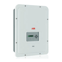
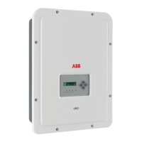
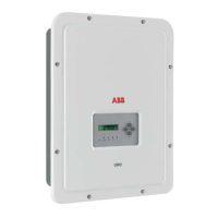
Configuration of independent channels (default configuration)
This conguration involves the use of the two input channels (MPPT) in
independent mode. This means that the jumpers
12
between the two
channels (positive and negative) of the DC input terminal board
12
must
not be installed and that the switch a01 situated on the communication
card
09
must be set to “IND” (see user interface).
13
12
CARD
J10
PC
OFF
TERM.
120
OFF
J8
ON
PMU
S2
S4
ON
PC
PMU
J9
PMU -T/R
J6
CARD
COM
PMU +T/R
GND COM
+5V OUT
R ON/OFF
J4
PC
SH
J7
PC +T/R
PC -T/R
GND
RTD3
RTD3
24V
-WTACH
J5
+WTACH
PT100
RTD2
RTD2
PT1000
J3
J2
PMU
CR2032
A2
COM
A2
RTD1
RTD1
A1
A1
COM
S6
NORM
S3
S7
COUNTRY/LANG SEL
K1
S8
MEMORY
ALARM
NC
C
BT1
NO
S5
PAR IND SERV
A1
J16
J14
J11
AN2 AN1
V
mA
V
mA
S1
a01
S5
PAR IND
+
Configuration of parallel-connected channels
This conguration involves the use of the two input channels (MPPT)
connected in parallel. This means that the jumpers
12
between the two
channels (positive and negative) of the DC input terminal board
13
must
be installed and that the switch a01 situated on the communication card
09
must be set to “PAR” (see user interface).
13
12
CARD
J10
PC
OFF
TERM.
120
OFF
J8
ON
PMU
S2
S4
ON
PC
PMU
J9
PMU -T/R
J6
CARD
COM
PMU +T/R
GND COM
+5V OUT
R ON/OFF
J4
PC
SH
J7
PC +T/R
PC -T/R
GND
RTD3
RTD3
24V
-WTACH
J5
+WTACH
PT100
RTD2
RTD2
PT1000
J3
J2
PMU
CR2032
A2
COM
A2
RTD1
RTD1
A1
A1
COM
S6
NORM
S3
S7
COUNTRY/LANG SEL
K1
S8
MEMORY
ALARM
NC
C
BT1
NO
S5
PAR IND SERV
A1
J16
J14
J11
AN2 AN1
V
mA
V
mA
S1
a01
S5
PAR IND
+

 Loading...


