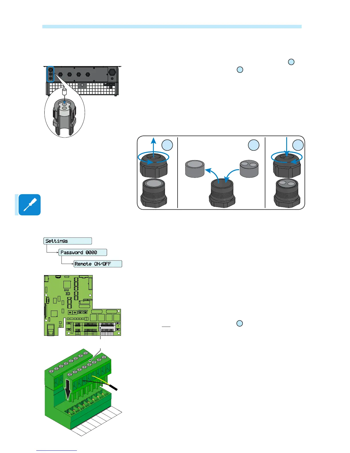
Connections to the communication card
Each cable that must be connected to the communication card
09
must
go through the three service cable glands
10
.
• One of size M25 that accepts a cable with cross-section of between
10mm and 17mm. Two-hole gaskets are supplied for insertion in the ca-
ble gland, which allow two separate cables with cross-section of up to
6mm to go through.
• Two of size M20 that accept a cable with cross-section of between
7mm and 13mm. Two-hole gaskets are supplied for insertion in the cable
gland, which allow two separate cables with cross-section of up to 5mm
to go through.
Remote control connection
The connection and disconnection of the inverter to and from the grid can
be controlled through an external control.
The function must be enabled in the relevant menu. If the remote control
function is disabled, the switching on of the inverter is dictated by the
presence of the normal parameters that allow the inverter to connect to
the grid.
If the remote control function is operating, besides being dictated by the
presence of the normal parameters that allow the inverter to connect to
the grid, the switching on of the inverter also depends on the state of the
R ON/OFF terminal compared to the GND COM terminal present on the
connector a11 of the communication card
09
.
When the R ON/OFF signal is brought to the same potential as the GND
COM signal (i.e. by making a short circuit between the two terminals of
the connector), this causes the inverter to disconnect from the grid.
The remote control OFF condition is shown on the display.
The connections of this control are made between the “R ON/OFF” input
and “GND COM”.
Since this is a digital input, there are no requirements to be observed
as regards cable cross-section (it only needs to comply with the sizing
requirement for passing cables through the cable glands and the terminal
connector).
Settings
Remote ON/OFF
ENTER
Password 0000
ENTER
CARD
J10
PC
OFF
TERM.
120
OFF
J8
ON
PMU
S2
S4
ON
PC
PMU
J9
PMU -T/R
J6
CARD
COM
PMU +T/R
GND COM
+5V OUT
R ON/OFF
J4
PC
SH
J7
PC +T/R
PC -T/R
GND
RTD3
RTD3
24V
-WTACH
J5
+WTACH
PT100
RTD2
RTD2
PT1000
J3
J2
PMU
CR2032
A2
COM
A2
RTD1
RTD1
A1
A1
COM
S6
NORM
S3
S7
COUNTRY/LANG SEL
K1
S8
MEMORY
ALARM
NC
C
BT1
NO
S5
PAR IND SERV
A1
J16
J14
J11
AN2 AN1
V
mA
V
mA
S1
PMU -T/R
PMU +T/R
GND COM
+5V OUT
R ON/OFF
SH
PC +T/R
PC -T/R
a11

 Loading...