Input connection to the PV generator (DC side)
Once the preliminary checks have been made and it has therefore been
veried that there are no problems on the photovoltaic system, and once
the channel conguration has been chosen (parallel or independent), the
inputs can be connected to the inverter.
The connections can also be made with the wiring box
02
detached from
the inverter
03
that can be connected later for commissioning.
When working with the wiring box
02
detached, pay particular attention to outdoor installa-
tions, where the coupling connector must always be protected by installing the cover
04
on
its housing.
The DC side connections are different according to the wiring box used:
The basic and S2 models use cable glands whereas the S2F /S2X mod-
els uses quick t connectors (one for each pole of each string).
On the basic and S2 versions, the connection in parallel of the strings (array composition)
must take place upstream of the input in the inverter and must be made by technicians during
installation.
The S2F / S2X version accepts direct connection of the single strings,
with connectors accessible from the outside of the wiring box
02
.
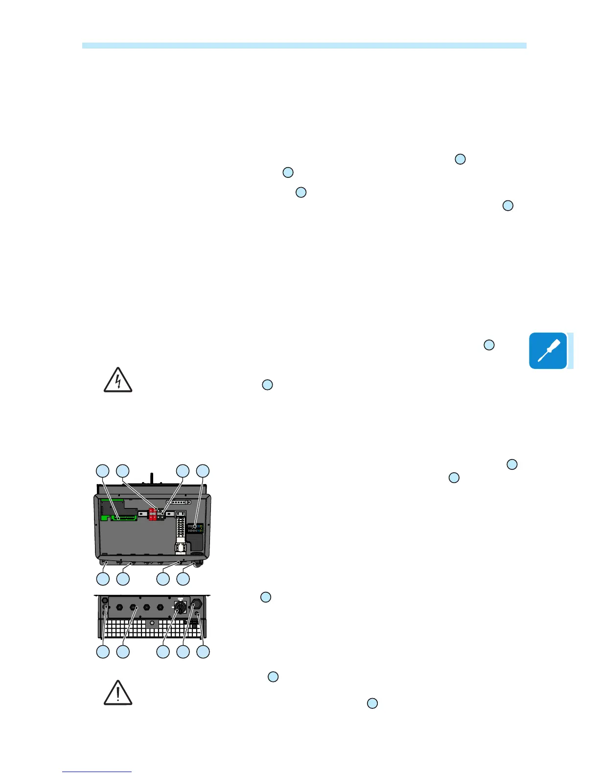
To prevent electrocution hazards, all the connection operations must be carried out with the
AC+DC disconnect switch
14
open and locked.
Connection of inputs on the Standard and S2 models
For these two models, connection with the DC input terminal board
13
is
made by inserting the cables in the DC cable glands
11
.
The maximum accepted cable cross-section ranges from 10 to 17 mm,
whereas each individual terminal of the terminal board accepts a cable
with cross-section of up to 50 mm
2
.
Unscrew the cable gland, remove the cover, insert the cable of suitable
cross-section and connect it to the terminals on the DC input terminal
board
13
.
Once the connection to the terminal board is complete, screw in the ca-
ble gland rmly and check the tightness.
The DC input terminal block
13
accepts connection of copper cables. If aluminium cables are
used, bimetallic cable terminals of a suitable type must be used to connect the aluminium
cables to the contacts in the DC input terminal block
13
.
09 13 12 17
10 11 14 16
10 11 14 16 21

 Loading...