- 11 - UMC100-FBP
Universal Motor Controller
UMC100-FBP
Technical Description
V 6
FieldBusPlug / Issue: 03.2012
181716151413121110
DIDIDIDIDIDI
24V
240
543210OutVV
Power
T1
8
DO
1
7
DO
0
6
DO
C
5
DO
C
9
DO
2
8765 9T2 Ca Cb
UMC100
READY
MOT.O N
FAUL T
Relay
230V AC
1A
Inputs
24VDC
DC
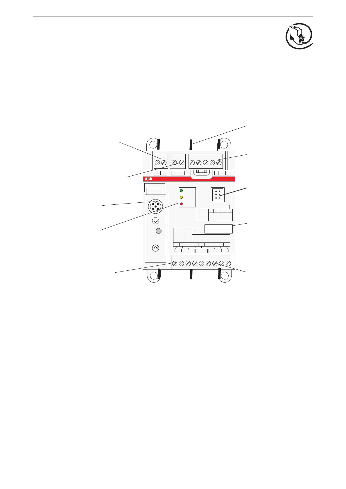
Connecting terminals
for the relay outputs
Connecting terminals
for PTC sensors
Current path
(for measuring
the motor current)
Connecting terminals
for the digital outputs
Plug connection
for the Control Panel
Connector
for the FieldBusPlug
Front label,
e.g. for slave address
24 V DC, GND
Supply voltage
Connecting terminals
for communication with
the IO modules
The UMC100 follows the profile for motor management starters as defined in the PNO profile sheet for
low voltage switchgear devices.
After powering on, the UMC100 performs a self-test of its hardware and checks the configuration for
consistency.
In the event of a failure, a self-test fault is generated and signalled. After a successful self-test the UMC
enters the operational state.
Description of Components
UMC100-FBP
The following diagram shows the terminals, monitoring and operating elements of the UMC100-FBP
LEDs
green READY = operation
yellow MOT.ON = motor on
red FAULT = overload,
failure
 Loading...