- 18 -UMC100-FBP
Universal Motor Controller
UMC100-FBP
Technical Description
FieldBusPlug / Issue: 03.2012
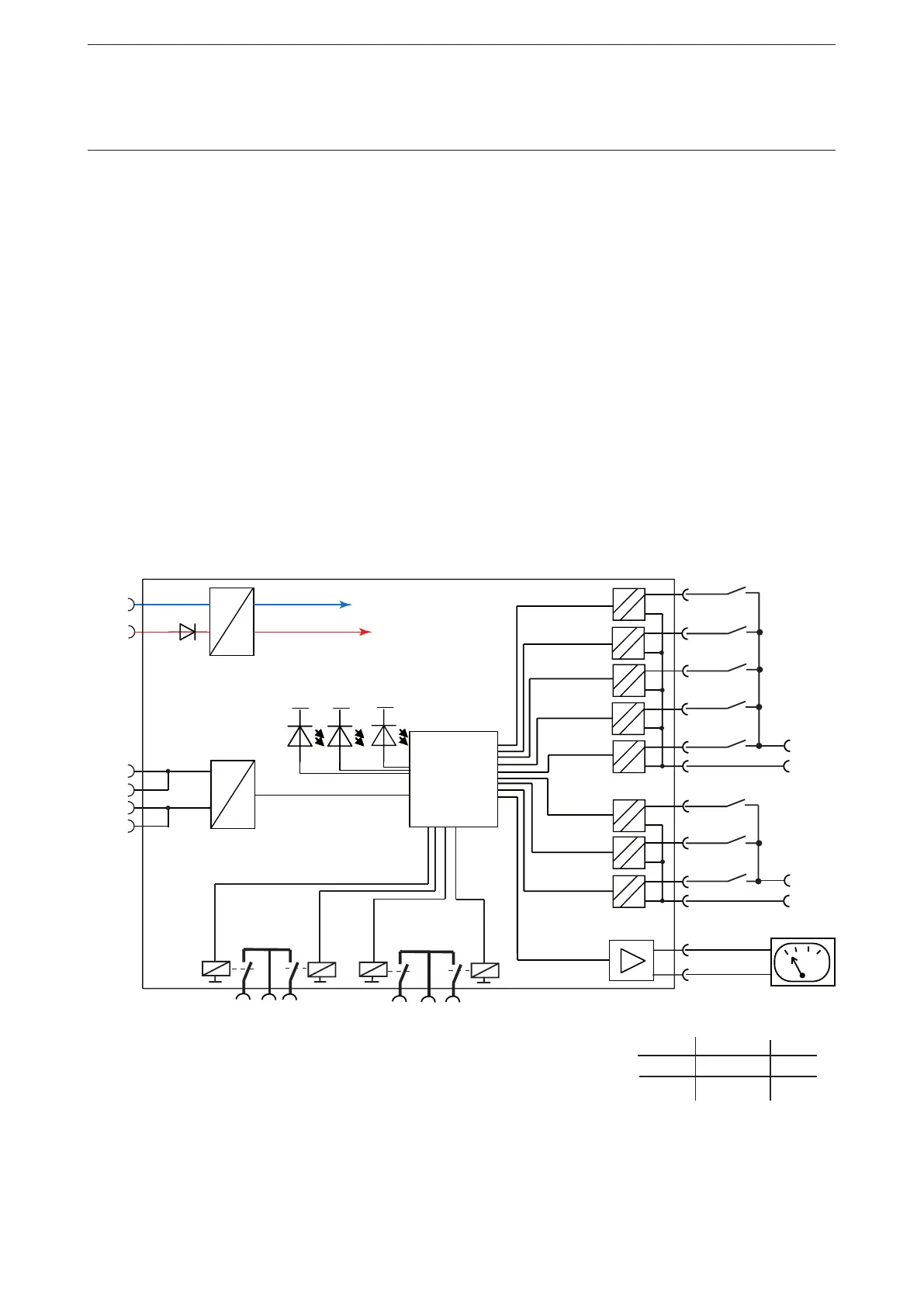
Wiring DX1xx Inputs and Outputs
The diagram below shows the block diagram and wiring for both the DX111 and the DX122 modules.
The digital inputs are galvanically isolated.
The common ground for the inputs 1DI0-4 must be connected to 1DIZ.
The common ground for the inputs 2DI5-7 must be connected to 2DIZ.
If no separate grounds are necessary, 1DIZ and 2DIZ can be connected to each other.
The relay outputs groups 1DO1/1DO2 and 2DO1/2DO2 have separate roots each.
The analogue output (AO+/AO-) is intended to drive an analogue instrument which can be used to display
the motor current. It can be adjusted as a current or voltage output.
Open wire and short-circuit faults are detected.
Supported output levels are:
• 0/4 - 20 mA
• 0 - 10 mA
• 0 - 10 V
The output is scaled in a way that a motor current of 0% results in 0% at the output and a motor current
of 200% results in 100% output level.
Example if the output is set as voltage output:
0% motor current -> U
out
=0 V, 200% motor current -> U
out
= 10 V.
Wiring diagram of the DX111-FBP and DX122-FBP module.
Logic
/
µC
24VDC
Warn
Diag
GND
AO+
Error
int. supply
1DI 1
1DI 2
1DI 3
1DI 4
2DI 6
2DI 7
2DI Z
1DOC
1DO0
1DO1
2DOC
2DO2
2DO3
RX / TX
1CA
2CA
1CB
2CB
AO-
2DI 5
1DI Z
L+
L-
L+
L-
DX111 +24VDC GND
DX122 230VAC N
L+ L-
 Loading...