- 23 - UMC100-FBP
Universal Motor Controller
UMC100-FBP
Technical Description
FieldBusPlug / Issue: 03.2012
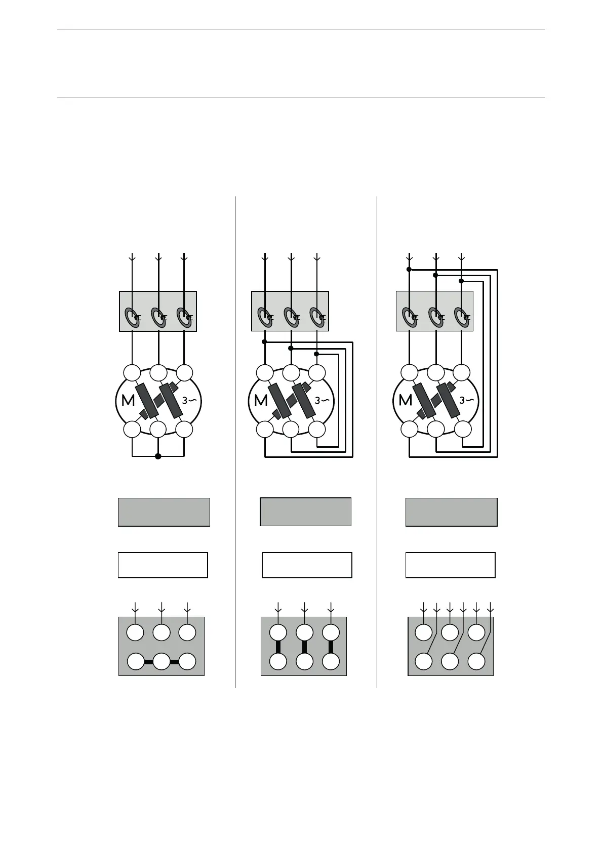
Motor Wiring
Have a look at the wiring of the motor to set the correct nominal current I
e
for perfect motor protection.
Example:
For inner delta wiring the parameter Current Factor can be changed to 1.73 to display the actual currents
on the Control Panel and in the control system. The delta 3 circuitry is normally used for larger motors to
reduce the current transformer size.
U2
W2
V2
V1 W1 U1
UMC
U2 W2 V2
V1 W1 U1
400 V / 690 V
W2
U1
U2
V1 W1
V2
UMC
U2 W2 V2
V1 W1 U1
400 V / 690 V
V1 W1 U1
W2
U2 V2
UMC
U2 W2 V2
V1 W1 U1
400 V / 690 V
Star
Power line: 690 V
Delta
Power line: 400 V
3 wiring
Power line: 400 V
Example for motor:
Motor rating plate
Example for motor:
Motor rating plate
Example for motor:
Motor rating plate
4.9 A / 2.8 A
4.9 A / 2.8 A 4.9 A / 2.8 A
Parameter
Set Current = 2.80
Parameter
Set current = 4.90
Parameter
Set current = 2.80*
Terminal box Terminal box Terminal box
I
P
= 2.8 A / I
SC
= 2.8 A I
P
= 4.9 A / I
SC
= 4.9 A I
P
= 4.9 A / I
SC
= 2.8 A
I
SC
=
I
P
I
SC
=
I
P
I
SC
=
I
P
* 0.577
I
P
I
P
I
P
2CDC 342 020 F0209
I
P
= Actual current / phase
I
SC
= Set current
* With voltage module you must set I
e
to 1.7 and the current factor to 4.9 A.
Related Parameters:
•Nominal current Ie1
•Nominal current Ie2 (for two speed starters only)
 Loading...