- 19 - UMC100-FBP
Universal Motor Controller
UMC100-FBP
Technical Description
FieldBusPlug / Issue: 03.2012
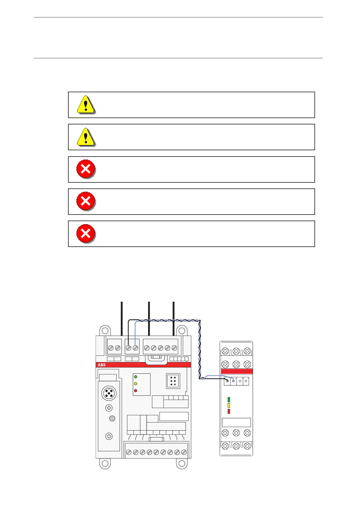
Connecting the VI15x Voltage Module
The modules VI150 and VI155 allows to measure the motor supply voltage, cosphi (power factor) and to
calculate thereof the active power and other values.
There are two module variants. The VI155 module can be used in grounded (TN) and
ungrounded (IT) networks.
The VI150 module can only be used in grounded networks (TN).
When using a voltage module the phase order at the UMC must be L1 to L3 from left
to right looking from top. See the image below.
Note that the connection cables for voltage measurement (terminals marked with L1,
L2, L3) may require additional cable protection
Don't connect any cable to the VI1xx terminals marked with NC (not connected)
Note that a distance of 10mm left from the terminal L1 and right from the terminal L3
to the next device might be required for voltages >230VAC or > 400VAC respectively
depending on the equipment mounted left and right of the module.
The module is connected via terminals Ca and Cb (see below) to the UMC100. It is possible to mount the
module separately from the UMC100.
181716151413121110
DIDIDIDIDIDI
24V
240
543210Ou tVV
Power
T1
8
DO
1
7
DO
0
6
DO
C
5
DO
C
9
DO
2
8765 9T2 Ca Cb
UMC100
READY
MOT.ON
FAUL T
Relay
230V AC
1A
Inputs
24VDC
DC
VI150
1Ca 1Cb
2Ca 2Cb
RDY
Diag
ERR
Relay DO
230VAC/1A
0V 24V DC NC
DOC DO0 NC
NC L2 NC
L1 NC L3
L1 L2 L3
 Loading...