EasyManua.ls Logo

Acer Aspire Z5600 Series User Manual

Acer Aspire Z5600 Series
210 pages
To Next Page IconTo Next Page
To Previous Page IconTo Previous Page
Page #66 background imageLoading...
Page #66 background image
56 Chapter 3
Removing the Web Camera Board
1. See “Removing the Home Button Board” on page 55.
2. Remove two (2) screws securing the Web Camera Board as shown.
3. Gently lift out the Web Camera Board and turn it over.
CAUTION: Do not use excessive force when removing the Web Camera Board.
4. Disconnect the cable underneath.
Step Size Quantity Screw Type
Web Camera Board SCREW M2.0*4 2

Table of Contents

Question and Answer IconNeed help?

Do you have a question about the Acer Aspire Z5600 Series and is the answer not in the manual?

Acer Aspire Z5600 Series Specifications

General IconGeneral
BrandAcer
ModelAspire Z5600 Series
CategoryDesktop
LanguageEnglish

Summary

System Specifications

Hardware Specifications and Configurations

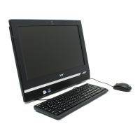
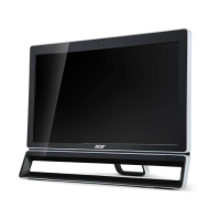
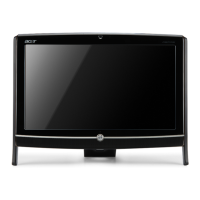
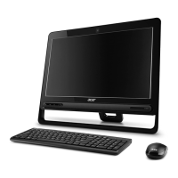
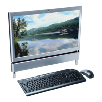
Lists detailed hardware specifications and configurations for the system.

System Utilities

BIOS Setup Utility

Describes the BIOS setup utility for hardware configuration and system settings.

Navigating the BIOS Utility

Provides instructions on how to navigate through the BIOS setup menus and options.

Advanced

Accesses advanced BIOS options for configuring system features.

Advanced Chipset Features

Details chipset settings and configuration within the advanced BIOS menu.

Security

Contains parameters for safeguarding and protecting the computer.

Setting a Password

Provides step-by-step instructions for setting user or supervisor passwords in BIOS.

PC Health

Monitors system temperature, voltage, and fan speed for CPU and system health.

Power

Configures device power management parameters within the BIOS.

Boot

Allows the user to decide the order of boot devices for the operating system.

Machine Disassembly and Replacement

Disassembly Requirements

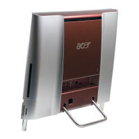
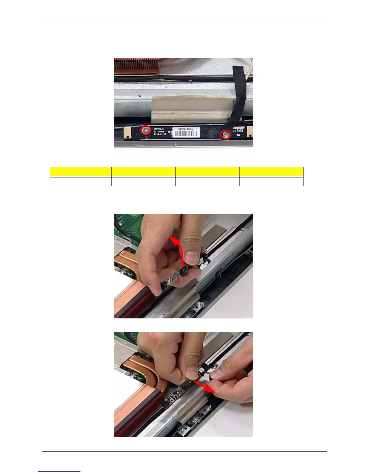
Lists the necessary tools and precautions before disassembling the computer.

Disassembly Process

Provides step-by-step instructions for disassembling the computer.

Disassembly Flowchart

Illustrates the sequence of steps for disassembling the computer.

Reassembly Procedure

Outlines the steps for reassembling the computer after component replacement.

Troubleshooting

Common Problems

Guides users through diagnosing and resolving common computer issues.

Jumper and Connector Locations

FRU (Field Replaceable Unit) List

Related product manuals