4263B
Guided T
our of
Panels
Front
Panel
This section
gives a
guided tour
of the
front panel.
F
or
a
detailed
description
of
each
key's
function, refer
to Chapter
3.
Each description
starting with
(Shift) is
the secondary
function
of
the
key
,
which
is
available
by
pressing the
blue shift
key.
(Refer to
\Shift
key
.")
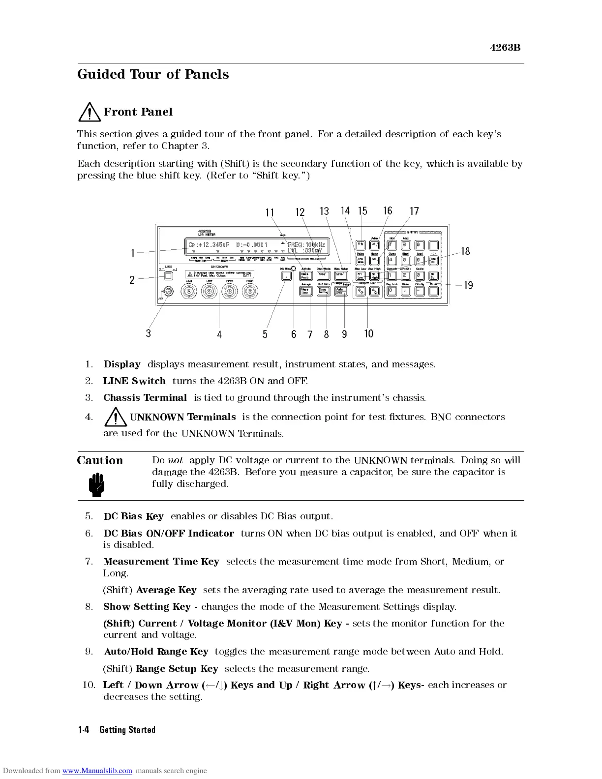
1.
Display
displays
measurement
result,
instrument
states
,
and
messages
.
2.
LINE
Switch
turns
the
4263B
ON
and
OFF
.
3.
Chassis
T
erminal
is
tied
to
ground
through
the
instrument's
chassis
.
4.
UNKNO
WN
T
erminals
is
the
connection
point
for
test
xtures
.
BNC connectors
are
used
for
the
UNKNOWN
T
erminals
.
Caution
Do
not
apply
DC voltage
or current
to
the
UNKNOWN
terminals
.
Doing
so
will
damage
the 4263B
. Before
you measure
a
capacitor
,
be
sure
the
capacitor
is
fully
discharged.
5.
DC
Bias
Key
enables or
disables DC
Bias output.
6.
DC
Bias
ON/OFF
Indicator
turns
ON
when
DC bias
output
is
enabled,
and
OFF
when
it
is disabled.
7.
Measurement Time K
ey
selects the measurement time mode from Short,
Medium, or
Long.
(Shift)
Average K
ey
sets the averaging rate
used to average the measurement result.
8.
Show Setting K
ey -
changes the mode of the Measurement Settings display
.
(Shift) Current / V
oltage Monitor (I&V Mon)
Key -
sets the monitor function for the
current and voltage.
9.
Auto/Hold Range Key
toggles the measurement range mode between Auto and Hold.
(Shift)
Range Setup Key
selects the measurement range.
10.
Left / Down Arrow (
/
#
)Keys and Up / Right Arrow (
"
/
!
)Keys-
each increases or
decreases the setting.
1-4 Getting Started

 Loading...