62 Rockwell Automation Publication 2094-UM001J-EN-P - March 2017
Chapter 4 Connector Data and Feature Descriptions
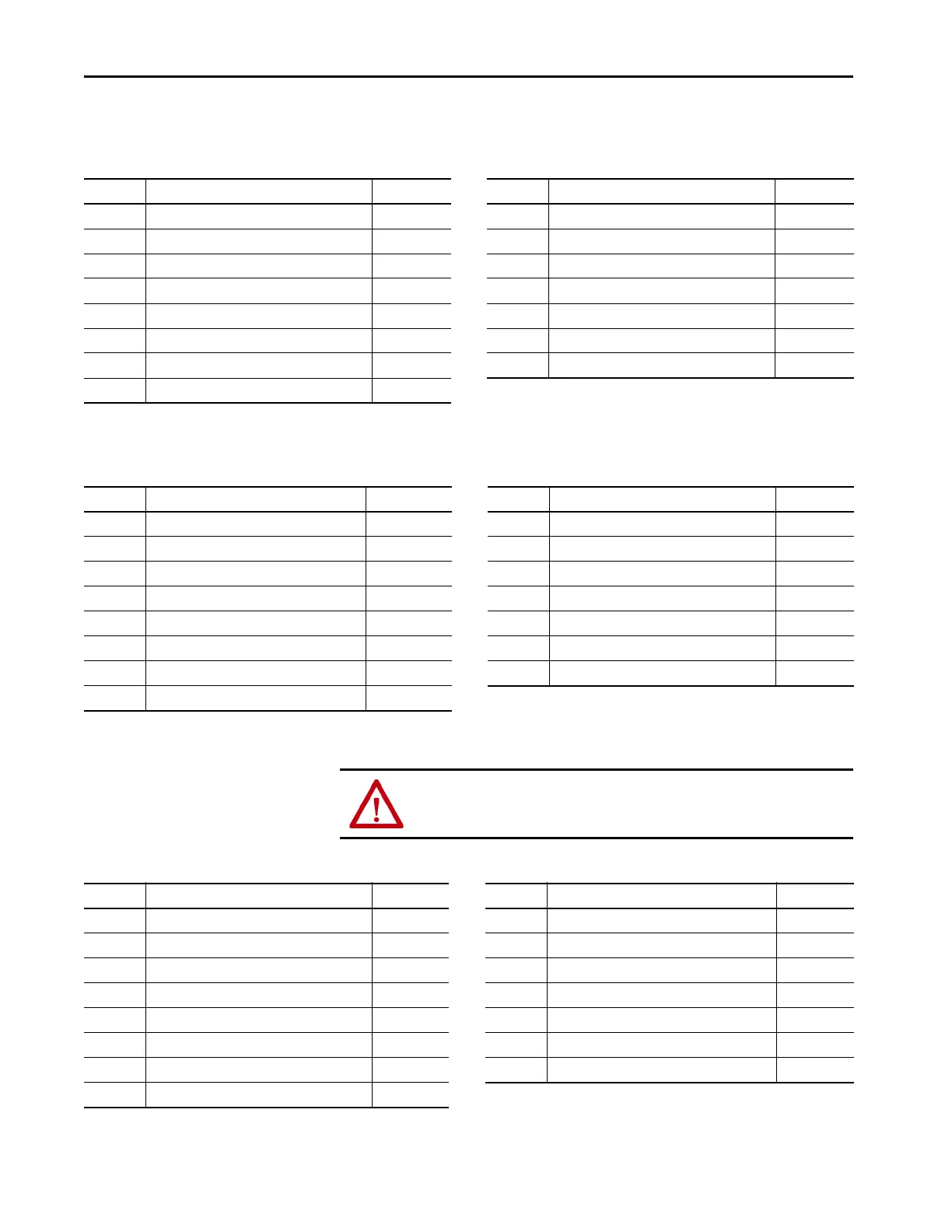
Motor Feedback Connector Pinout
Table 26 - Stegmann Hiperface (SRS/SRM)
Table 27 - TTL or Sine/Cosine with Index Pulse and Hall Commutation
Table 28 - Resolver Transmitter (transformation ratio = 0.25)
MF Pin Description Signal MF Pin Description Signal
1 Sine differential input+ SIN+ 9 Reserved –
2 Sine differential input- SIN- 10 Hiperface data channel DATA-
3 Cosine differential input+ COS+ 11 Motor thermal switch (normally closed)
(2)
TS+
4 Cosine differential input- COS- 12 Reserved –
5 Hiperface data channel DATA+ 13 Reserved –
6 Common ECOM 14 Encoder power (+5V) EPWR_5V
(1)
7 Encoder power (+9V) EPWR_9V
(1)
15 Reserved –
8Reserved –
(1) Determine which power supply your encoder requires and connect to only the specified supply. Do not make connections to both.
(2) Not applicable unless the motor has integrated thermal protection. Common (TS-) signal for thermal switch is tied to MF-6 (ECOM) in Bulletin 2090 cables.
MF Pin Description Signal MF Pin Description Signal
1 AM+ / Sine differential input+ AM+ / SIN+ 9 Reserved –
2 AM- / Sine differential input- AM- / SIN- 10 Index pulse- IM-
3 BM+ / Cosine differential input+ BM+ / COS+ 11 Motor thermal switch (normally closed)
(2)
TS+
4 BM- / Cosine differential input- BM- / COS- 12 Single-ended 5V hall effect commutation S1
5 Index pulse+ IM+ 13 Single-ended 5V hall effect commutation S2
6 Common ECOM 14 Encoder power (+5V) EPWR_5V
(1)
7 Encoder power (+9V) EPWR_9V
(1)
15 Reserved –
8 Single-ended 5V hall effect commutation S3
(1) Determine which power supply your encoder requires and connect to only the specified supply. Do not make connections to both.
(2) Not applicable unless the motor has integrated thermal protection. Common (TS-) signal for thermal switch is tied to MF-6 (ECOM) in Bulletin 2090 cables.
ATTENTION: To avoid damage to components, determine which power supply
your encoder requires and connect to either the 5V or 9V supply, but not both.
MF Pin Description Signal MF Pin Description Signal
1 Sine differential input+ S2 9 Reserved –
2 Sine differential input- S4 10 Resolver excitation R2
3 Cosine differential input+ S1 11 Motor thermal switch (normally closed)
(1) (2)
TS+
4 Cosine differential input- S3 12 Reserved –
5 Resolver excitation R1 13 Reserved –
6 Common ECOM 14 Reserved –
7 Reserved – 15 Reserved –
8Reserved –
(1) Not applicable unless the motor has integrated thermal protection. Common (TS-) signal for thermal switch is tied to MF-6 (ECOM) in Bulletin 2090 cables.
(2) If using 1326AB (resolver-based) motors, use 2090-K6CK-D15MF Low-profile Connector Kits that connect the filtered thermal switch (pins 16 and 17) to MF-11 and MF-6.

 Loading...

