30 Rockwell Automation Publication 2094-UM001J-EN-P - March 2017
Chapter 2 Plan the Kinetix 6000 Drive System Installation
Enclosure Selection
This example is provided to assist you in sizing an enclosure for your Bulletin
2094 drive system. The example system consists of these components:
• 6-axis Bulletin 2094 servo drive system
• Line Interface Module (LIM)
• ControlLogix® chassis and modules (controller)
Size the Bulletin 2094 servo drive and LIM module and use the results to
predict the amount of heat dissipated into the enclosure. You also need heat
dissipation data from other equipment inside the enclosure (such as the
ControlLogix controller). Once the total amount of heat dissipation (in watts)
is known, you can calculate the minimum enclosure size.
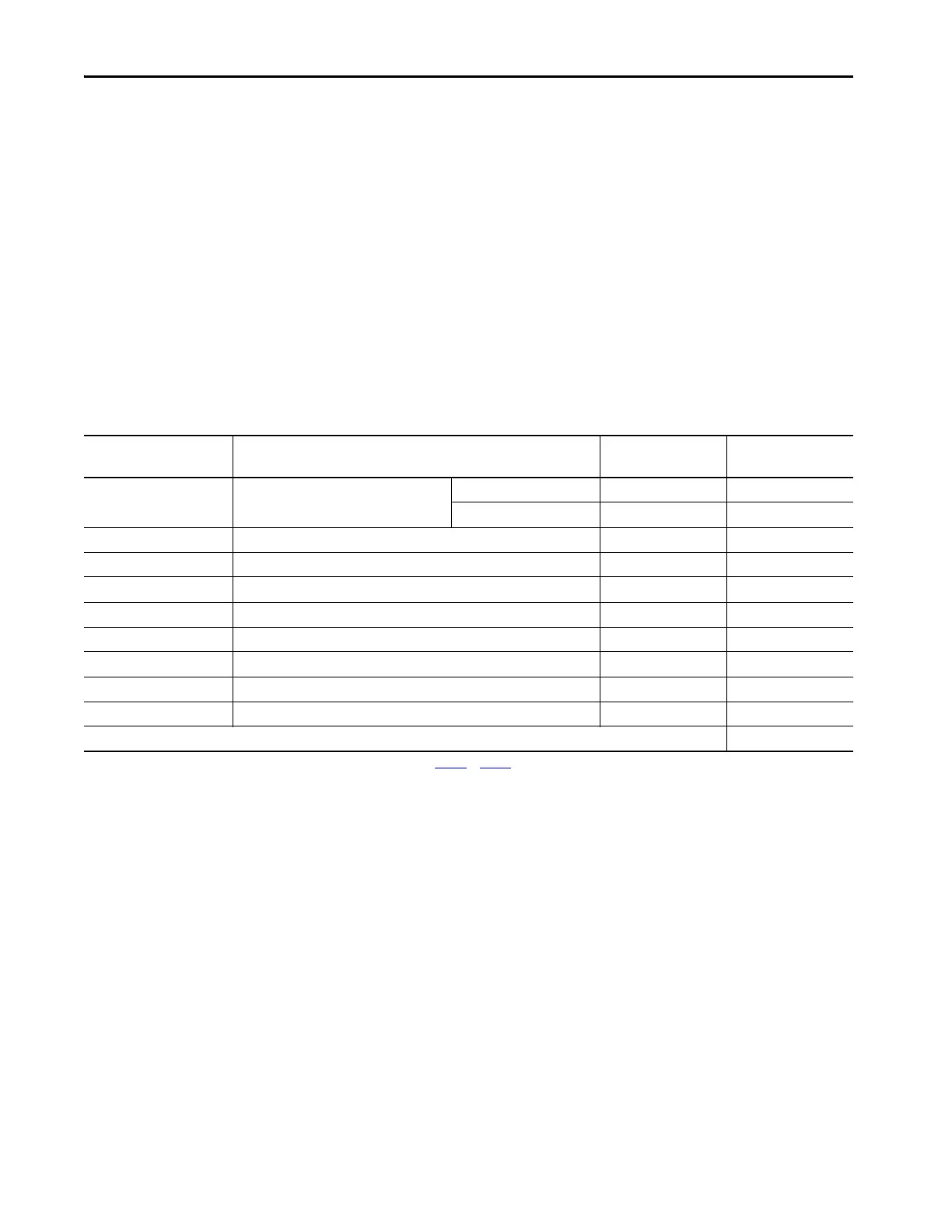
Table 10 - Bulletin 2094 System Heat Dissipation Example
Enclosure Component Description Loading
(1)
Heat Dissipation
(1)
watts
2094-BC02-M02-x
Integrated axis module (IAM),
400/460V
15 kW (converter section) 20% 44
15 A (inverter section) 40% 72
2094-BM02-x Axis module (AM), 400/460V, 15 A 60% 93
2094-BM02-x Axis module (AM), 400/460V, 15 A 60% 93
2094-BM01-x Axis module (AM), 400/460V, 9 A 40% 73
2094-BM01-x Axis module (AM), 400/460V, 9 A 40% 73
2094-BM01-x Axis module (AM), 400/460V, 9 A 20% 57
2094-BL25S Line interface module (LIM), 400/460V, 25 A; 24V DC 20 A 100% 43
2094-PRS6 Power rail, 460V, 6 axis N/A 0
2090-XB33-32 Resistive brake module (RBM), 33 A, 32 Ω N/A 30
Total Kinetix 6000 system wattage 578
(1) To determine heat dissipation specifications for your drive system components, refer to Tabl e 12 on page 32.

 Loading...

