136 Rockwell Automation Publication 2094-UM001J-EN-P - March 2017
Chapter 6 Configure and Start the Kinetix 6000 Drive System
Configure the Drive Modules
Follow these steps to configure the integrated axis module (IAM) and axis
modules (AM).
1. Verify that no power is applied to the IAM and AM modules and that
the communication cables are plugged into the appropriate connectors.
To verify communication, refer to Sercos Fiber-optic Cable Connections
on page 130
.
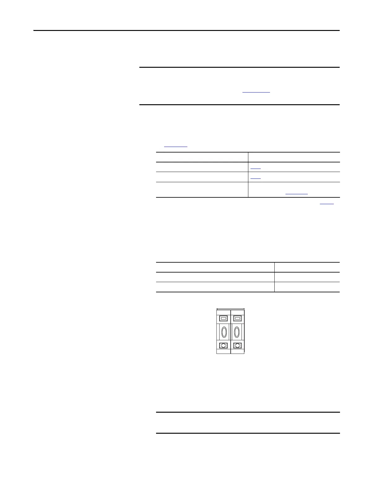
2. Set the base node address for the IAM module by setting the Node
Address switches.
Valid node addresses for Sercos communication are 01…99. The left
switch sets the most significant digit (MSD) and the right switch sets
the least significant digit (LSD).
Setting the base node address on the IAM module determines the node
address for the IAM (inverter) module. Node addressing for all slot
locations on the same power rail increment (from the IAM inverter) left
to right.
3. Cycle control power to initialize the IAM module.
IMPORTANT If you have one or more IDM power interface modules (IPIM) on your
power rail, refer to the Kinetix 6000M Integrated Drive-Motor System
User Manual, publication 2094-UM003
, for system configuration
information specific to the Kinetix 6000M IDM system.
To Configure Begin With
The IAM module step 2
Any AM module step 4
Kinetix 6000M IDM system
(1)
(1) Sercos fiber-optic cable connections for the Kinetix 6000M integrated drive-motor (IDM) system are on page 133.
Kinetix 6000M Integrated Drive-Motor User
Manual, publication 2094-UM003.
To Press
Increment the (MSD/LSD) node address The plus (+) switch.
Decrement the (MSD/LSD) node address The minus (-) switch.
IMPORTANT The base node address setting takes effect only after the IAM power
module is initialized.
Decrements MSD
MSD
Increments MSD
Decrements LSD
LSD
Increments LSD

 Loading...

