172 Rockwell Automation Publication 2094-UM001J-EN-P - March 2017
Chapter 7 Troubleshooting the Kinetix 6000 Drive System
IAM/AM Module Status Indicators
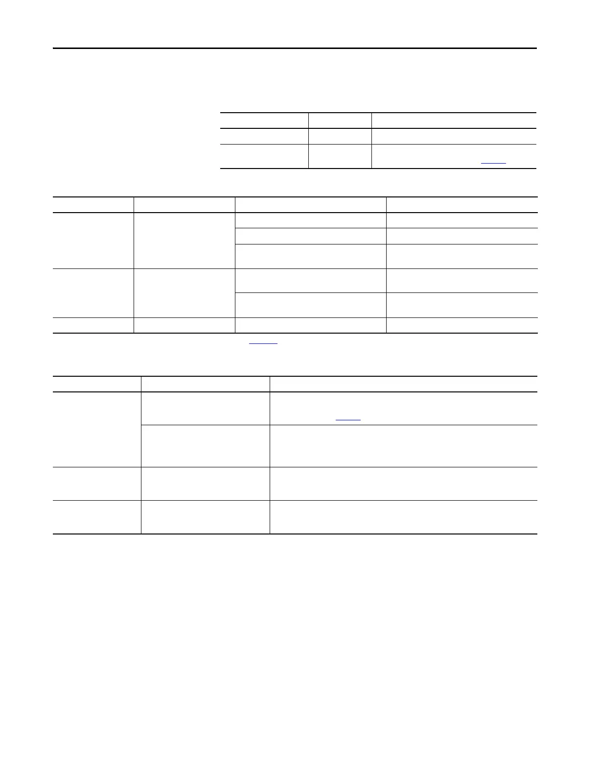
Table 103 - Drive Status Indicator
Table 104 - Comm Status Indicator
Table 105 - Bus Status Indicator
Drive Status Indicator Drive Status Possible Resolution
Off Normal, no faults N/A
Steady red Drive faulted
Refer to seven-segment error code and Kinetix 6000 Drive
System Error Codes troubleshooting on page 167.
Comm Status Indicator Drive Status Potential Cause Possible Resolution
Off No communication
(1)
Loose fiber-optic connection. Verify proper fiber-optic cable connections.
Broken fiber-optic cable. Replace fiber-optic cable.
Receive fiber-optic cable connected to Sercos
transmit connector and vice versa.
Check proper Sercos fiber-optic cable connections.
Flashing green Establishing communication
System is still in the process of establishing Sercos
communication.
Wait for steady green indicator.
Node address setting on the drive module does not
match Sercos controller configuration.
Verify proper node switch setting.
Steady green Communication ready No faults or failures. N/A
(1) Refer to Fiber-optic Cable Installation and Handling Instructions, publication 2090-IN010, for more information.
Bus Status Indicator Bus Status Condition
Off
No power or DC bus is not present.
• Normal when bus power is not applied.
• Fault exists, refer to seven-segment error code and Kinetix 6000 Drive System Error Codes
troubleshooting on page 167.
Bus power is present in follower IAM.
• Follower IAM module is not configured as CommonBus Follow in the Logix Designer
application.
• After DC bus voltage is applied, a 2.5 second delay before the indicator begins flashing green is
normal operation to provide the common-bus leader module time to complete precharge.
Flashing green
Bus power is present, axis disabled.
No faults.
Normal when:
• 24V is not applied to Hardware Enable Input (IOD-2).
• MSO instruction is not commanded in the Logix Designer application.
Steady green
Bus power is present, axis enabled.
No faults.
Normal when:
• 24V is applied to Hardware Enable Input (IOD-2).
• MSO instruction is commanded in the Logix Designer application.

 Loading...

