Integrated Motion on the EtherNet/IP Network
Rockwell Automation Publication MOTION-RM003I-EN-P - February 2018 23
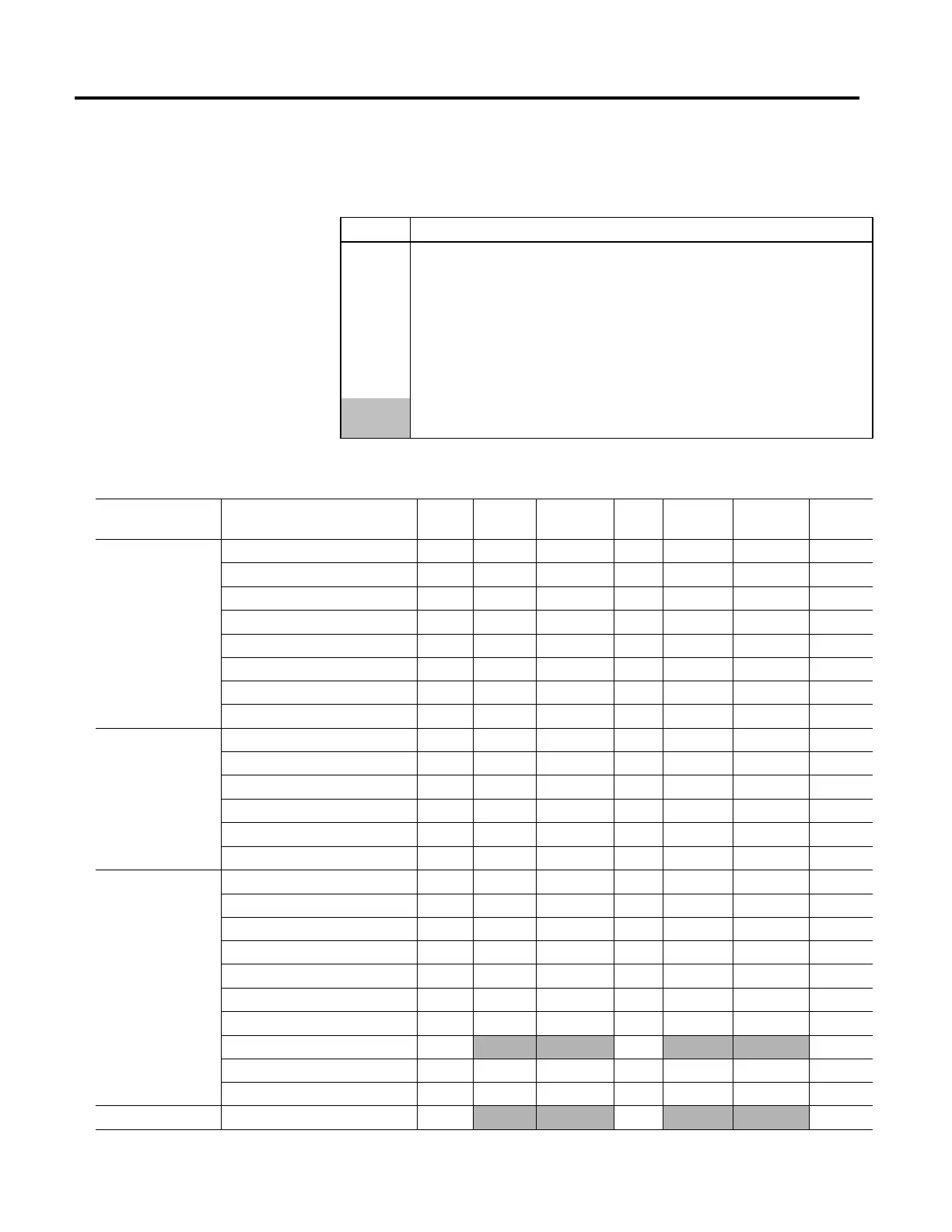
divided by type.
Use the following key to interpret the column entries:
Symbol Meaning
x
Control mode is compatible.
#
MSO and MDS execution initiate mutually exclusive modes of operation and execution is conditional on
mode.
*
Axis may be used as a master axis reference only for this instruction.
c
Axis may conditionally use Motion Planner instructions if enabled with MSO instruction, otherwise, it
errors.
Shaded areas denote that Multi-Axis Coordination Motion is designed and tested for position mode
operation but not specifically restricted to that axis configuration.
Category Motion Instruction Name Abbr. Feedback
Only
Freq.Cntrl
No Feedback
Pos.
Loop
Vel. Loop
Feedback
Vel. Loop
No Feedback
Torque
Loop
State Control
Motion Direct Drive On MDO
Motion Direct Drive Off MDF
Motion Servo On MSO
# x # # #
Motion Servo Off MSF
x x x x x
Motion Axis Fault Reset MAFR x x x x x x
Motion Axis Shutdown MASD x x x x x x
Motion Axis Shutdown Reset MASR x x x x x x
Motion Drive Start MDS
#
# # #
Event Control
Motion Arm Watch Position MAW x
x x
x
Motion Disarm Watch Position MDW x
x x
x
Motion Arm Registration MAR x
x x
x
Motion Disarm Registration MDR x
x x
x
Motion Arm Output Cam MAOC x
x x
x
Motion Disarm Output Cam MDOC x
x x
x
Move Control
Motion Redefine Position MRP x c x c c c
Motion Axis Home MAH x
x c
c
Motion Axis Jog MAJ
c x c c
Motion Axis Move MAM
c x c c
Motion Change Dynamics MCD
c x c c
Motion Axis Stop MAS x x x x x x
Motion Axis Gear MAG * c x c c *
Motion Master Driven Axis Control MDAC * c x c c *
Motion Axis Position Cam MAPC * c x c c *
Motion Axis Time Cam MATC
c x c c
Multi-Axis Coordinate Motion Coordinated Linear Move MCLM
c x c c
 Loading...


