Interpret the Attribute Tables
Rockwell Automation Publication MOTION-RM003I-EN-P - February 2018 95
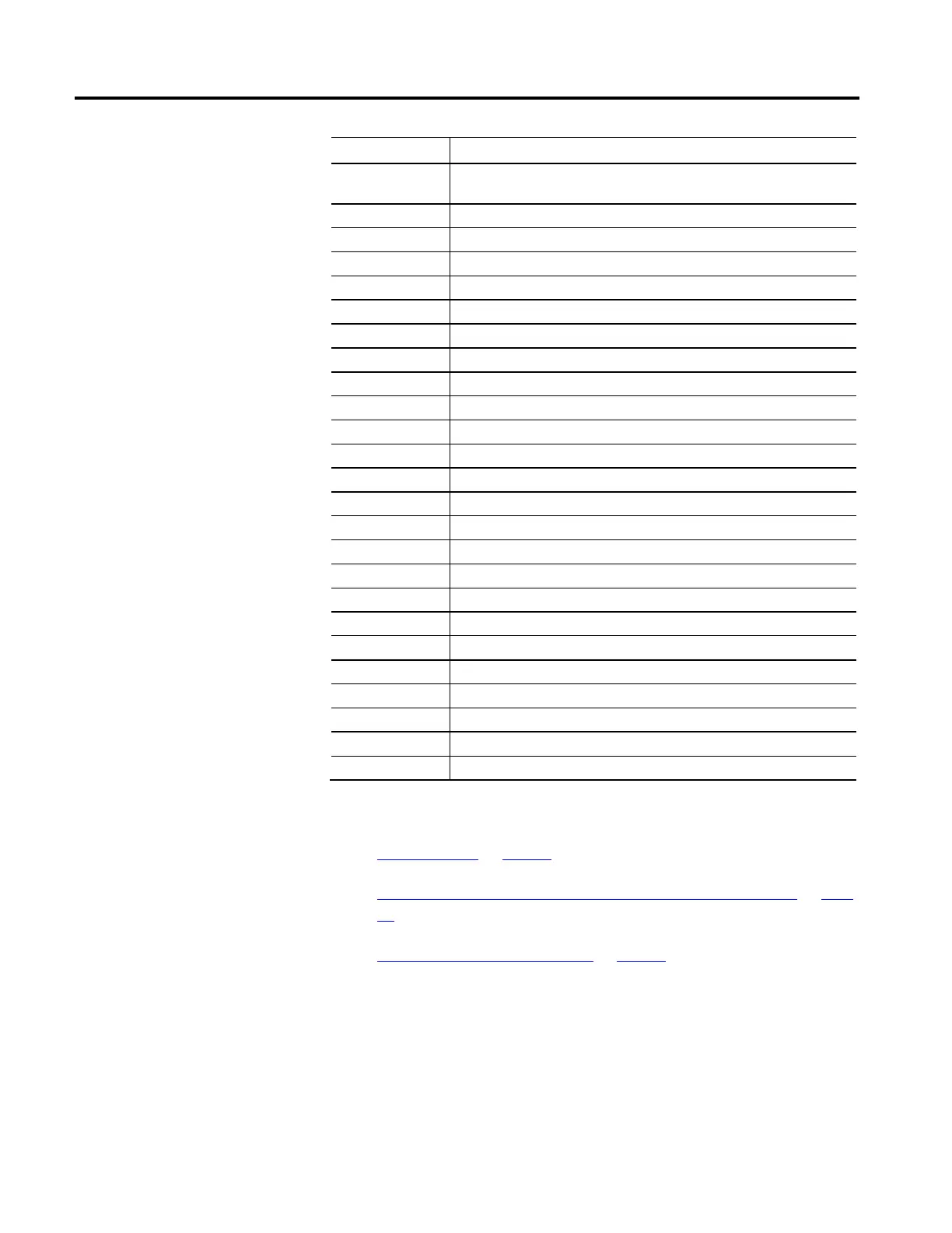
Key Description
AOP
Add-on Profile. Logix Designer component that can be separately installed and used for
configuring one or more modules.
Derived Implementation rules follow another attribute
Drive Scaling Drive device supports drive scaling functionality
DSL Hiperface DSL (feedback type)
E21 EnDat 2.1 (feedback type)
E22 EnDat 2.2 (feedback type)
E Encoder-based control, a feedback device is present
!E Encoderless or sensorless control, a feedback device in not present
HI Hiperface (feedback type)
HD Hiperface DSL®
IM Rotary or Linear Induction Motor (motor type)
INT Integrated
IPM Rotary or Linear Interior Permanent Magnet motor (motor type)
Linear Absolute Feedback Unit - meter; Feedback n Startup Method- absolute
Linear Motor Linear PM motor or Linear Induction motor (motor type)
NV Motor NV or Drive NV (motor data source)
P### P### refers to the related PowerFlex® drive parameter.
PM Rotary or Linear Permanent Magnet motor (SPM or IPM) (motor type)
Rotary Absolute Feedback Unit - rev; Feedback n Startup Method- absolute
Rotary Motor Rotary PM motor or Rotary Induction motor (motor type)
Safety only Applicable to Integrated Motion on the EtherNet/IP network safety devices only
SC Sine/Cosine (feedback type)
SL Stahl SSI (feedback type)
SPM Rotary or Linear Surface Permanent Magnet motor (motor type)
TT Digital AqB (feedback type)
See also
Control Modes on page 16
Identify Motion Axis Attributes Based on Device Control Codes on page
95
Interpreting the Attribute Tables on page 87
The following table provides an alphabetical list of all Motion Axis Attributes
specific to the CIP Drive data type. The table identifies whether the attribute is
Required (R), Optional (O), or Conditional (C), in implementation based on the
Device Function Code. Attributes that are not applicable for a device function
code are denoted by a dash (-).
The Device Function Codes are:
Attributes Based on Device
Function Codes
 Loading...


