Publication 1763-RM001C-EN-P - October 2009
550 Knowledgebase Quick Starts
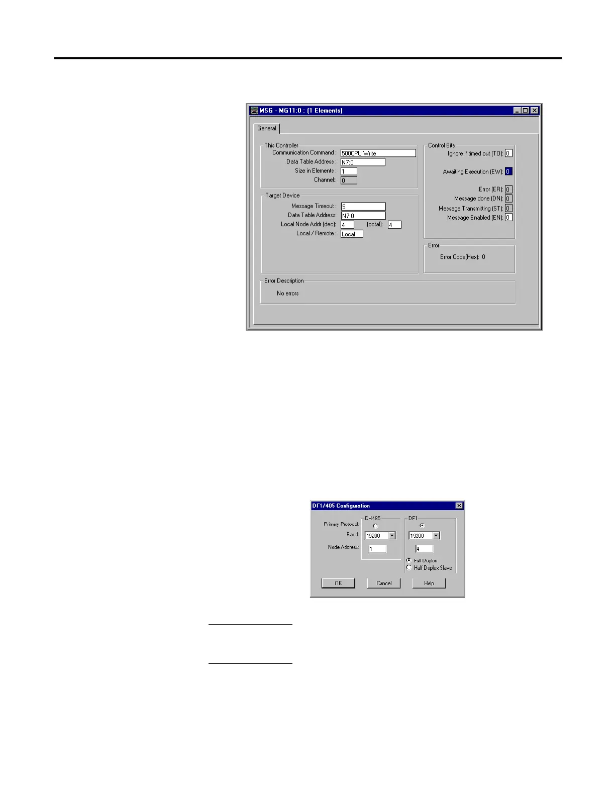
MSG Setup Screen
Micrologix 1000 (Node 4) Ladder Logic
No ladder logic is required in the destination processor, however the
communications channel must be configured to match the source
processor. Since the default settings for the ML1500 communications
channel is DF1 protocol, 19,200 Kbaud the ML1000 must be configured to
match. (See Below)
Micrologix 1000 Channel Configuration
Important Note:Do not connect to ML1000 directly using a
1761-CBL-AM00 cable.
Important Note:
After the ladder logic has been entered into the ML1100
and the ML1000 channel configuration has been changed, in order for this
example to function connect the controllers using a 1761-CBL-PM02 cable,
leave connected until the COMM 0 LED on the ML1100 starts to blink.
efesotomasyon.com - Allen Bradley,Rockwell,plc,servo,drive

 Loading...


