6 - 7
INSTALACION ELECTRICA ELECTRICAL SYSTEM
6.1.3 CONTROL CONTINUIDAD ALTERNADOR
Con el motor parado:
◆ Quiete la tapa de inspección derecha, véase 7.1.2
(DESMONTAJE TAPAS DE INSPECCION DERECHA
E IZQUIERDA).
◆ Desconecte el conector cables alternador (1).
◆ Con un tester de bolsillo compruebe la continuidad en-
tre los cables amarillos (G) del estator.
Compruebe también el aislamiento del soporte del es-
tator.
Valor estándard de la resistencia: 0,1 -1Ω
Valor estándard de la resistencia entre cables y so-
porte estator:
∞ (infinito)
6.1.4 REGULADOR DE TENSION
◆ Extraiga la cola, véase 7.1.3 (DESMONTAJE COLA).
◆ Desconecte el conector (2).
◆ Destornille y retire el tornillo (3) y desconecte el termi-
nal del cable (4) y del cable (5).
Durante la instalación vuelva a conectar am-
bos cables (4) y (5).
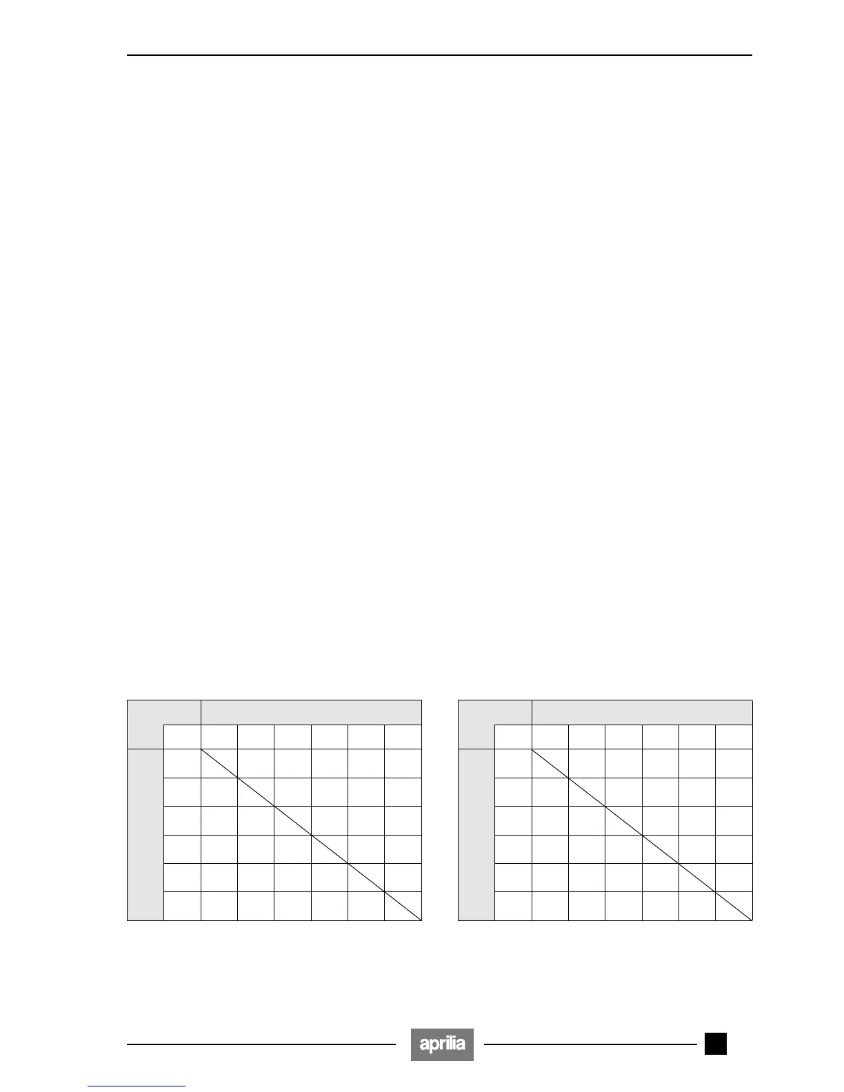
◆ Con un tester de bolsillo (escala x 1 kΩ), mida (desde
el lado regulador) la resistencia entre los cables indi-
cados en la tabla a continuación.
Si la resistencia que se ha medido no resulta ser correc-
ta, sustituya el regulador.
Este método de medida es aproximado; si es
posible compruebe el funcionamiento correc-
to de la recarga utilizando otro regulador que
funcione con seguridad.
Terminal positivo (+) del tester sobre:
GGGRBR/V
Terminal negativo (–)
del tester sobre:
G
∞∞∞∞∞
G
∞ ∞∞∞∞
G
∞∞ ∞∞∞
R
∞∞∞ ∞∞
B
∞∞∞∞
1-∞
R/V
∞∞∞∞
1-∞
a
a
6.1.3 CHECKING THE ALTERNATOR CONTINUITY
With the engine off, proceed as follows:
◆ Remove the right inspection cover, see 7.1.2 (REMO-
VING THE RIGHT AND LEFT INSPECTION CO-
VERS).
◆ Disconnect the alternator cable connector (1).
◆ Check the voltage continuity between the yellow ca-
bles (G) of the stator, by means of a pocket tester.
Check also the insulation of the stator support.
Standard resistance value: 0,1-1Ω
Standard value of the resistance between the stator
cables and support:
∞ (infinite)
6.1.4 VOLTAGE REGULATOR
◆ Remove the rear part of the fairing, see 7.1.3 (REMO-
VING THE REAR PART OF THE FAIRING).
◆ Disconnect the connector (2).
◆ Unscrew and remove the screw (3) and disconnect the
terminal of the cables (4) and (5).
Upon reassembly, connect both cables (4)
and (5).
◆ Take (from the regulator side) the resistance between
the cables indicated in the following table (scale x 1
kΩ), by means of a pocket tester.
If the resistance is not correct, change the regulator.
This measuring method is approximate: if
possible, check the correct operation of the
recharging system by using another regula-
tor, the operation of which must be certainly correct.
Positive terminal (+) of the tester on:
GGGRBR/V
Negative terminal (–)
of the tester on:
G
∞∞∞∞∞
G
∞ ∞∞∞∞
G
∞∞ ∞∞∞
R
∞∞∞ ∞∞
B
∞∞∞∞
1-∞
R/V
∞∞∞∞
1-∞
a
a
 Loading...