Velocity - Controller Structure
Function description88
Version: 1.5
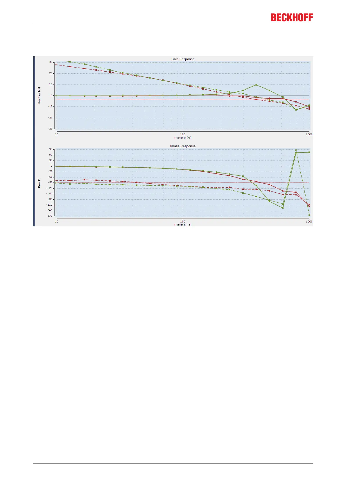
The Bode diagram shows that system peaking at approx. 380 Hz disappears after activation of the Velocity
Observer, since the open-loop phase shift is lower with activated Velocity Observer from approx. 100 Hz.
The result is a larger phase margin:
The green line was recorded with the Observer switched off, the red line with the Observer switched on. The
dashed line shows the open-loop phase shift.
If interfering resonances occur in the lower frequency range, it may be useful to reduce the bandwidth of the
Velocity Observer. For axes with very rigid coupling between motor and load it may be useful to increase the
bandwidth.
Advanced Mode
Advanced mode is recommended for axes with high narrow-band resonance frequencies, for which a notch
filter is considered. The bandwidth of the Velocity Observer should be lower than the resonance frequency
by a factor 2 ... 3.
Compared with the notch filter, the Velocity Observer benefits from a greater tolerance, even though the
resonance frequencies can vary somewhat over time, or depending on the position.
20.1.5.3 Practical example
Request:
The spindle of a machine tool has a resonance frequency at 800 Hz.
In advanced mode the bandwidth of the Velocity Observer is set to 300 Hz.
Aim of the setting:
The Velocity Observer should improve the bandwidth of the velocity controller. Once the velocity controller
has been "calmed", e.g. by reducing the Velocity Observer bandwidth, one can try increasing the
proportional gain, in order to achieve a better response of the velocity controller.

 Loading...


