32
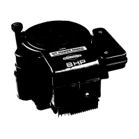
Blower Housing
1. See Figure 33. Remove four hex flange screws (A) to
release blower housing (B) from crankcase.
NOTE: Bottom screw on cylinder head side also
captures cylinder heat shield. Bottom screw on
crankcase side also captures flywheel guard.
33
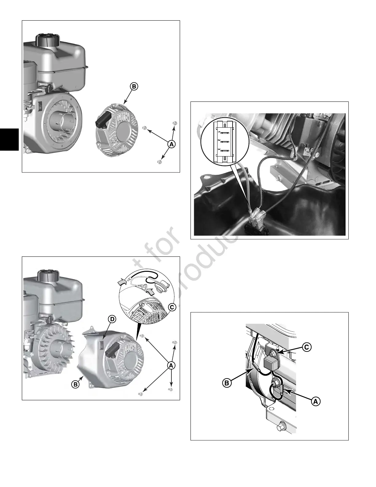
2. If equipped with rotary stop switch (C), release ground
wire ring terminal from top blower housing screw on
crankcase side and disconnect one-place wire
connector between stop switch and armature.
3. If equipped with rocker stop switch (D), pull blower
housing away from crankcase just far enough to access
stop switch spade terminals and proceed as follows:
A. See Figure 34. Disconnect socket of red wire ring
terminal (stop switch ground) from terminal 1.
B. Disconnect socket of armature/remote magneto
stop terminal wire from terminal 2.
C. If equipped, disconnect socket of low oil sensor
module wire from terminal 3.
34
Low Oil Sensor Module (If Equipped)
NOTE: If engine is equipped with electric start, oil sensor
module is removed with starter motor.
1. See Figure 35. Disconnect one-place wire connector
(A) between oil sensor and oil sensor module.
35
34
4
 Loading...