Low Oil Sensor (If Equipped)
1. Inspect low oil sensor for damage. Verify that float
mechanism moves freely without sticking.
2. Inspect rubber washer on oil sensor fitting for cuts,
tears, or signs of deterioration. Replace as necessary.
3. Route oil sensor wire and fitting through crankcase hole.
4. See Figure 81. Install two hex flange screws (A) to
fasten oil sensor to threaded bosses inside crankcase.
Tighten screws as follows.
Low Oil Sensor Screws
TorqueModels
50-70 lb-in (5.7-7.9 N-m)130G00, 131G00, 13R200
71-124 lb-in (8-14 N-m)13U100, 13U200
5. From outside crankcase, install hex flange nut (B) on
fitting. Tighten nut as follows.
Low Oil Sensor Nut
TorqueModels
30-50 lb-in (3.4-5.7 N-m)130G00, 131G00, 13R200
71-124 lb-in (8-14 N-m)13U100, 13U200
81
Governor Crank
1. Verify cleanliness of governor gear. If cylinder was
reconditioned or resized, be sure all honing grit has
been removed.
2. Manually rotate governor gear in both directions to verify
that it moves freely without roughness or sticking.
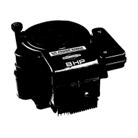
3. See Figure 82. Install governor cup with flat washer
onto governor gear shaft (A).
82
83
4. From inside crankcase, insert governor crank with flat
washer thru hole at top of crankcase (B).
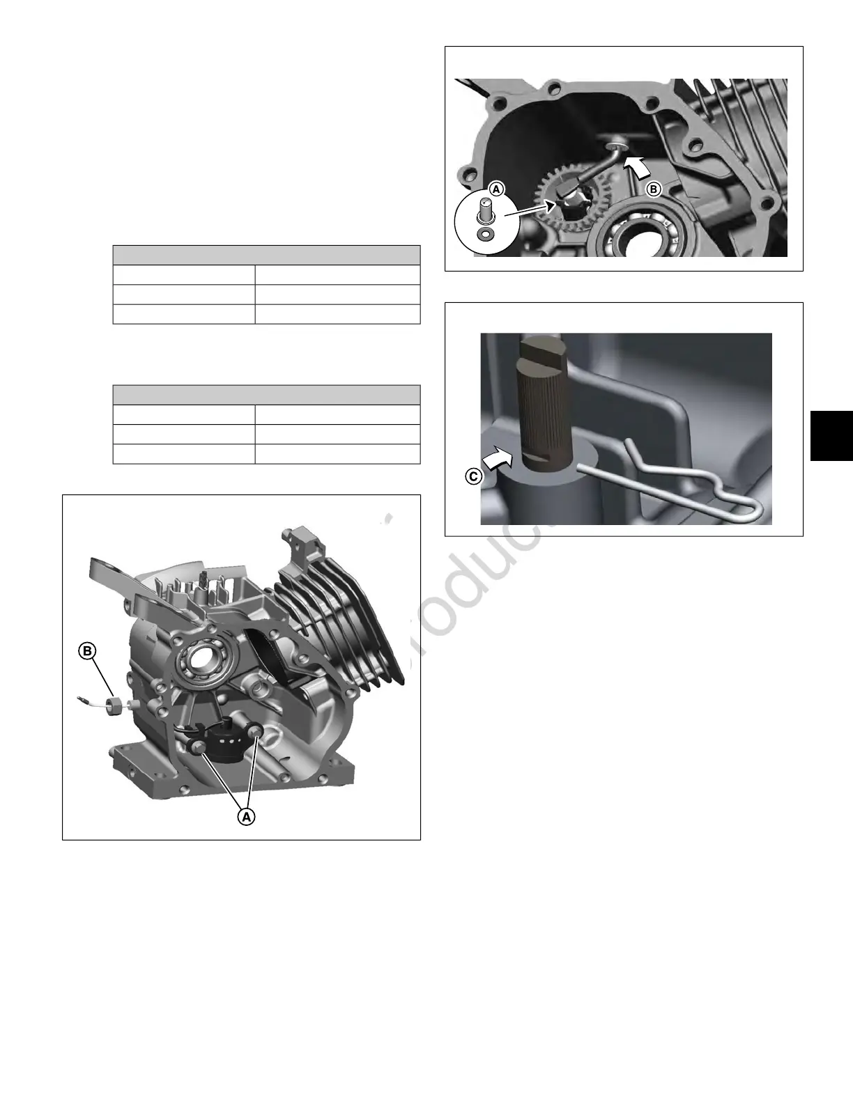
5. See Figure 83. Install spring clip, so that the straight
leg engages groove in governor crank (C).
6. Verify that governor crank rotates freely without sticking.
Crankcase Cover
PTO Bearing/Oil Seal
1. Feel bearing bore for smoothness. Use fine steel wool
or crocus cloth to remove any burrs or minor
imperfections.
2. Apply a thin film of clean engine oil to bearing bore and
OD of new bearing.
3. With the inside facing upward, support crankcase cover
on wooden blocks on deck of arbor press.
4. With the bearing manufacturer's identification facing
the inside of the crankcase cover, place bearing into
bearing bore.
5. Place suitable bearing driver on outer race of bearing.
6. Center bearing driver under ram.
7. Verify that assembly is square, so that bearing is not
damaged during installation.
65
6
 Loading...