5. Remove O-ring seal from gear case. Discard O-ring
seal.
6. Note orientation of gear case before removal.
NOTE: Gear case is installed in the 3 o'clock, 9 o'clock,
or 12 o'clock positions.
7. Remove four hex flange screws (G) to release gear
case from crankcase cover.
8. Remove gasket from crankcase cover. Discard gasket.
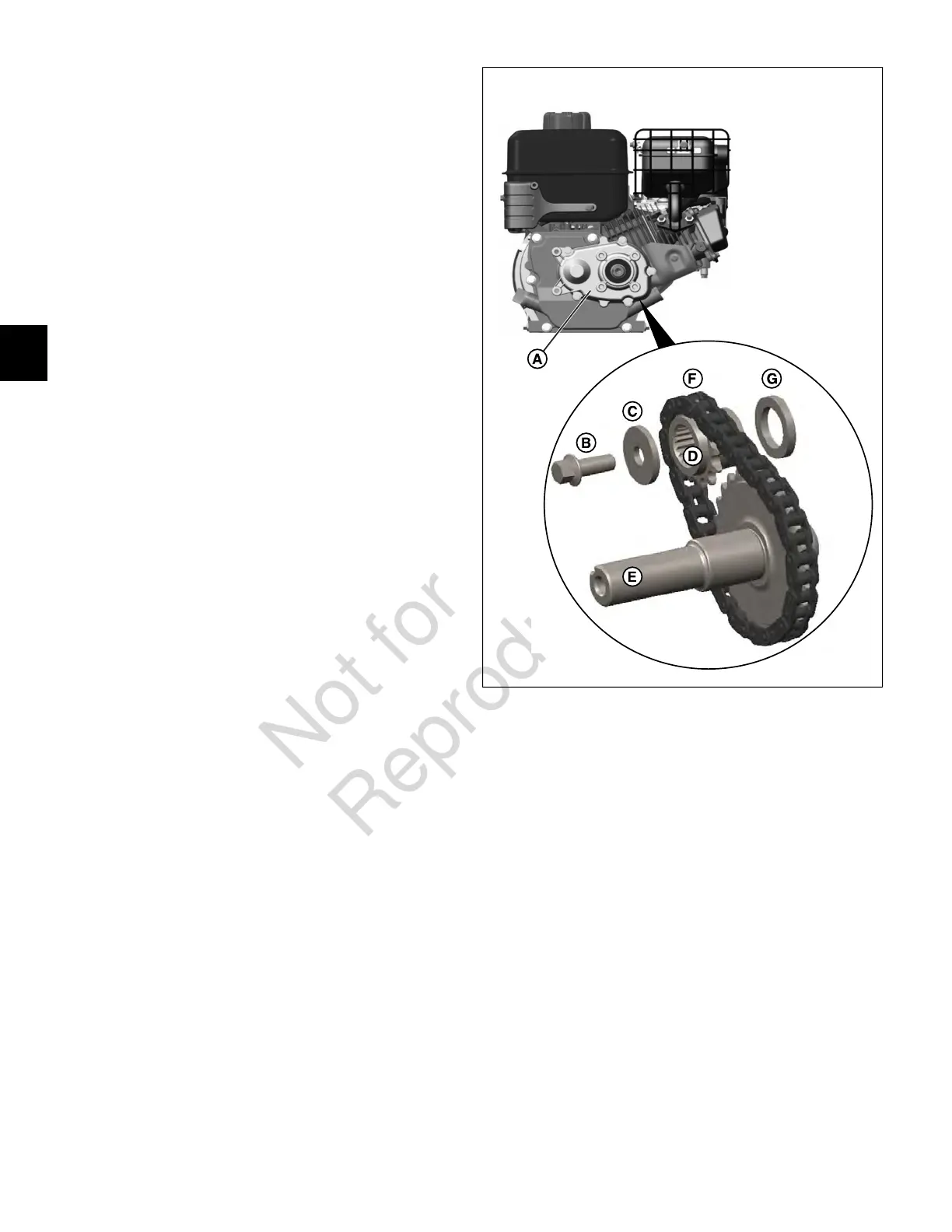
2:1 Gear Reduction Unit
1. See Figure 40. Remove five screws to release gear
cover (A) from crankcase cover.
NOTE: If gear cover sticks, use a soft hammer to lightly
tap area adjacent to two locating pins (6 o'clock and 12
o'clock positions).
2. Remove gear cover gasket from locating pins.
3. Remove two locating pins from crankcase cover flange
and set aside.
4. Remove hex flange screw (B) with flat washer (C) from
end of crankshaft.
40
5. Slide sprocket (D) from crankshaft while pulling output
shaft (E) from crankcase cover bore.
6. Remove chain (F) from sprocket and output shaft.
7. Remove spacer (G) from crankshaft.
36
4
 Loading...