cleanliness. Do not use a wire brush or the holes may
be enlarged.
7. If present, verify that set of oil drain back holes at top
of piston skirt are clean and open.
Connecting Rod
1. Thoroughly clean parts in a non-volatile cleaning
solution or solvent. Follow up with a thorough wash in
hot soapy water.
2. Blow dry with low pressure compressed air.
3. Verify that oil holes in connecting rod shank and at top
of piston pin bore are clean and open.
Inspection
Piston and Pin
1. Carefully inspect the piston for damage or excessive
wear. Proceed as follows:
A. Inspect the piston for cracks. Pay special attention
to the area around the pin bores and oil drain back
holes beneath the piston crown.
B. Check piston for cracked, broken or bent ring lands.
C. Check piston skirt for cracks, gouges, deep
scratches or heavy scoring.
D. Check piston head for evidence of burning, etching
or melting.
E. Look for marks or imprints caused by contact with
valves.
NOTE: A piston with superficial wear marks, minor
scratching or mild scoring may continue to be used.
2. Lightly oil a good piston pin and insert it into the piston
pin bore to feel for proper fitment. The pin should slide
in and out without binding, but also without pivoting or
rocking.
60
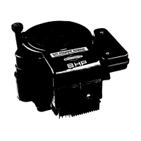
3. See A of Figure 60. Using an inside micrometer or dial
vernier caliper, measure the piston pin bore diameter
at two locations- parallel and perpendicular to the
crankshaft. Replace the piston if either measurement
is 0.711 inches (18.06 mm) or more.
4. See B of Figure 60. Using an outside micrometer,
measure the outside diameter of the piston pin at two
locations- parallel and perpendicular to the crankshaft.
Replace piston pin if either measurement is at the reject
size shown below.
Piston Pin Diameter
Reject SizeModels
0.707 in (17.96 mm) or less130G00, 131G00, 13R200
0.708 in (17.97 mm) or less13U100, 13U200
5. Run your index finger around the edge of the piston
crown to feel for dings, nicks or burrs. Lightly file the
edge of the crown to remove any defects.
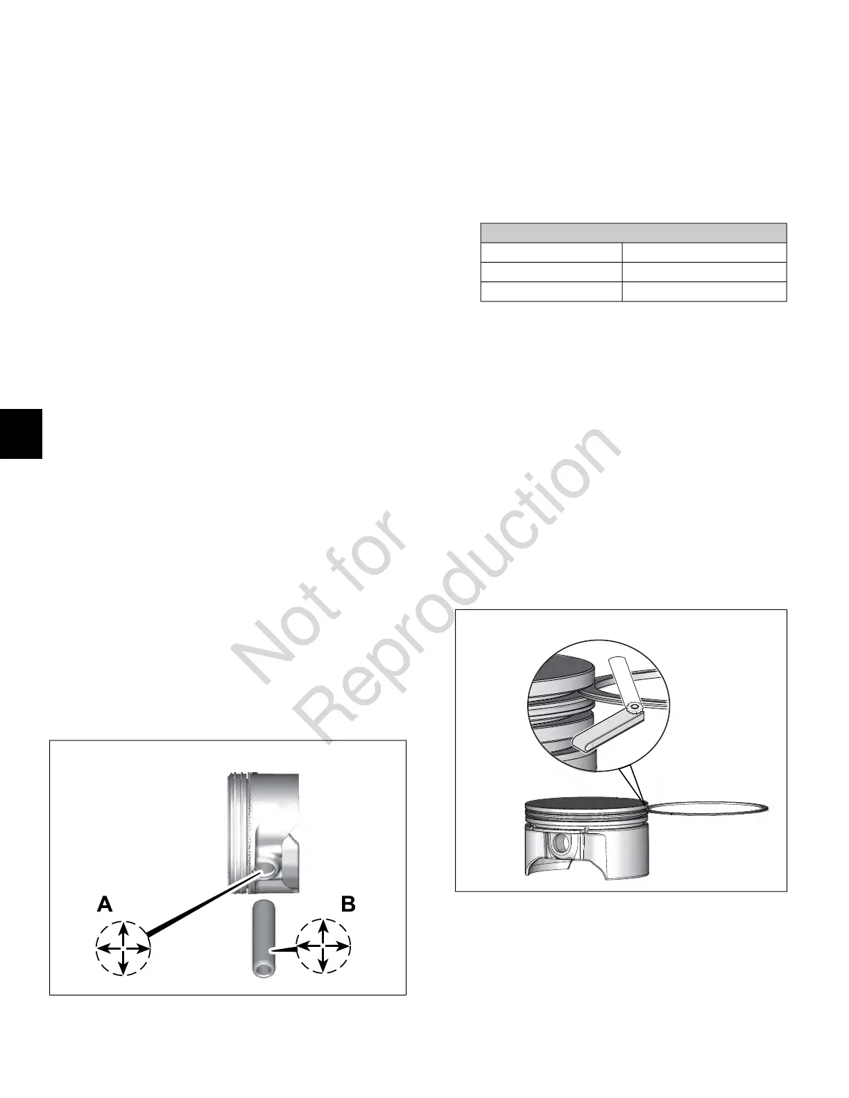
6. Measure the piston ring side clearance as follows:
NOTE: Worn ring grooves result in high oil consumption
and blow-by of exhaust gases. Blow-by of exhaust
gases contaminates the engine oil supply, and reduces
engine efficiency by weakening the combustion seal
necessary for efficient transfer of energy to the piston.
A. See Figure 61. Insert the edge of a new
compression ring into the top piston ring groove.
Insert a feeler gauge between the upper surface of
the ring and the ring land.
61
B. Since the grooves wear unevenly, repeat this check
at several locations around the piston ring groove
circumference.
C. Discard the piston if any measurement is 0.009
inches (0.23 mm) or more.
54
6
 Loading...