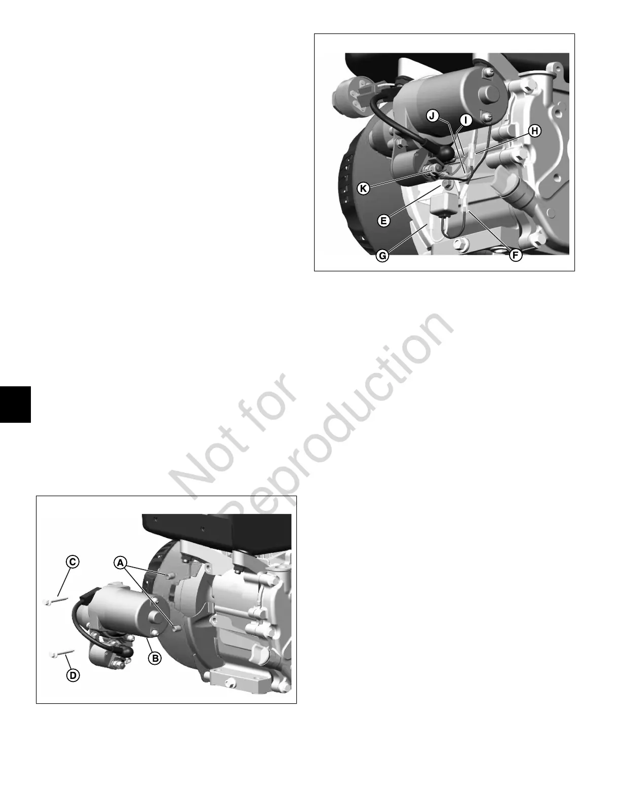
Starter Motor (If Equipped)
1. Install connector and spade terminal to key switch on
trim panel.
2. See Figure 125. Install two locating pins (A) into holes
in crankcase.
3. With the stator wires routed over the top of the starter
motor, install starter motor (B) onto locating pins.
4. Install top starter motor screw (C) capturing brown key
switch ground wire ring terminal, and tighten to 80-110
lb-in (9-12.4 N-m).
5. Install bottom starter motor screw (D) and tighten to
80-110 lb-in (9-12.4 N-m).
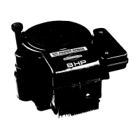
6. See Figure 126. If equipped, install low oil sensor
module as follows:
A. Install hex flange screw (E) to fasten oil sensor
module bracket to flywheel guard. Tighten screw
to 30-80 lb-in (3.4-9 N-m).
B. Connect one-place wire connector (F) between oil
sensor module and key switch spade contact.
C. Connect one-place wire connector (G) between oil
sensor module and oil sensor.
7. Route yellow key switch wire and orange key switch
wire behind starter motor to area of starter solenoid.
8. Connect yellow key switch wire terminal to starter
solenoid black wire terminal (H).
9. If stator wires terminate in a ring terminal, move to step
10. If stator wires terminate in a 2-place jumper wire
connector, proceed as follows:
NOTE: Ring terminal supersedes 2-place jumper wire
connector on late model engines.
125
126
A. Install flat washer and red jumper wire (I) ring
terminal onto starter solenoid post.
B. Coil extra length of jumper wire behind starter
motor.
C. Connect 2-place jumper wire connector between
stator and starter solenoid post.
D. Move to step 11.
10. Install flat washer and red stator wire ring terminal (I)
onto starter solenoid post.
11. Install orange key switch wire ring terminal (J) onto
starter solenoid post.
12. Install flat washer, lock washer, and hex nut (K) onto
starter solenoid post. Tighten hex nut to 30-40 lb-in
(3.4-4.5 N-m).
86
8
 Loading...