NOTE: If stud is difficult to remove, apply suitable
penetrating oil to threads, and then work stud in
and out until it moves freely.
E. Remove stud from cylinder head. Remove hex
flange nuts from stud.
F. Install new stud, so that the stepped side goes into
the cylinder head.
G. Repeats steps 2(B) and 2(C).
H. Rotating outside nut in a clockwise direction, tighten
stud as follows.
Carburetor Stud
TorqueModels
50-70 in-lbs (5.7-7.9 N-m)130G00, 131G00, 13R200
44-62 lb-in (5-7 N-m)13U100, 13U200
3. Replace a muffler stud as follows:
A. Retrieve the two hex nuts removed from the studs
during muffler removal.
B. Thread first nut onto stud.
C. Thread second nut onto stud until it makes firm
contact with the first.
D. Rotate inside nut in a counter-clockwise direction
until stud is loose.
NOTE: If stud is difficult to remove, apply suitable
penetrating oil to threads, and then work stud in
and out until it moves freely.
E. Remove stud from cylinder head. Remove hex nuts
from stud.
F. Install new stud, so that the side with the shorter
threads goes into the cylinder head.
G. Repeats steps 3(B) and 3(C).
H. Rotating outside nut in a clockwise direction, tighten
stud as follows.
Muffler Stud
TorqueModels
40-60 in-lbs (4.5-6.8 N-m)130G00, 131G00, 13R200
35-62 lb-in (4-7 N-m)13U100, 13U200
Assembly
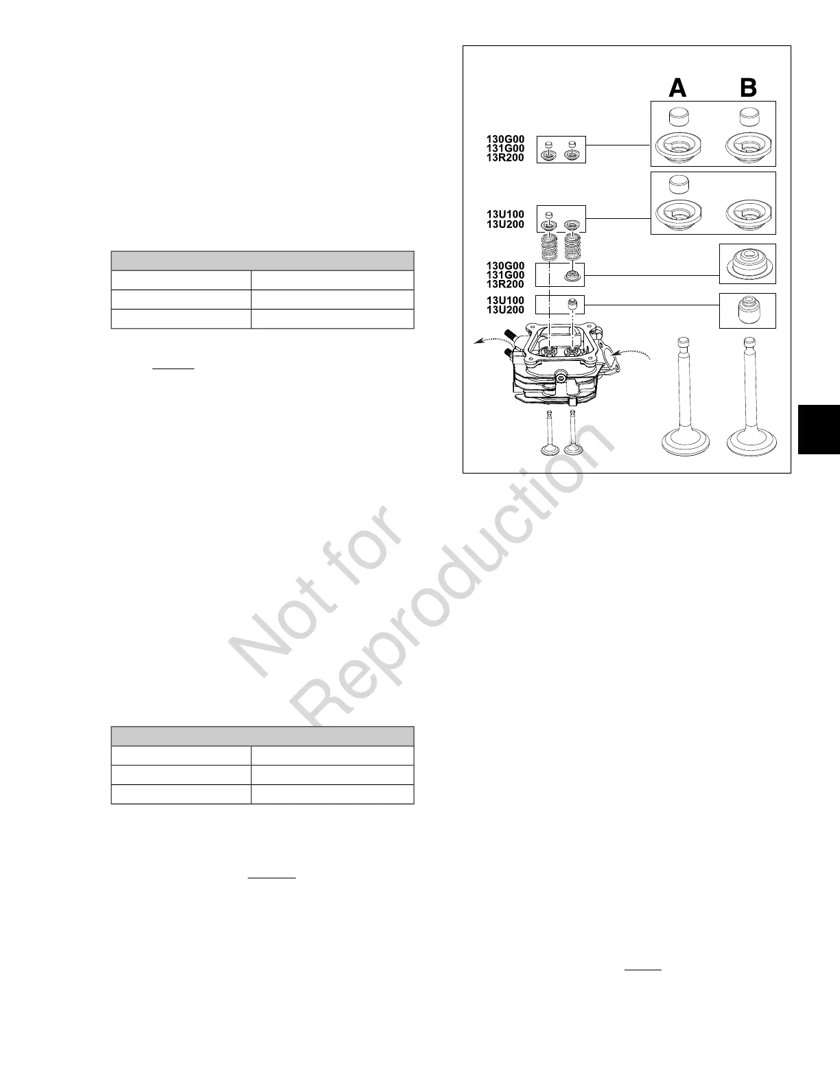
1. See A of Figure 57. Install exhaust valve assembly as
follows:
A. Apply a suitable engine assembly lube to the valve
stem.
NOTE: If the valves were not tagged during
disassembly, remember that the exhaust valve
always has the smaller valve face diameter.
57
B. From the bottom of the cylinder head, insert the
valve stem into the valve guide.
C. To distribute the assembly lube evenly around the
valve stem and guide, hand spin the valve as it is
installed. Work the valve back and forth in the bore
to verify that it slides smoothly and seats properly.
D. Using denatured alcohol or other suitable
degreaser, thoroughly clean valve face, valve seat,
valve guide, and end of valve stem of any excess
assembly lube.
E. Install valve spring over the valve stem and valve
guide.
F. Set the valve spring retainer on top of the valve
spring. Using thumbs to compress valve spring,
guide the end of the valve stem through the larger
offset hole in the valve spring retainer. Continue
pressing down until the smaller center hole engages
the valve stem groove.
G. Verify that the axis of the valve spring is parallel to
the valve stem. A cocked valve spring will result in
premature valve guide wear.
H. Lightly tap the end of the valve stem once or twice
with a soft mallet to ensure that valve spring retainer
is tightly seated in the valve stem groove.
I. Install valve cap on end of valve stem.
2. See B of Figure 57. Install intake valve assembly as
follows:
51
6
 Loading...