NOTE: Only the top compression ring side clearance
needs to be checked.
Piston Rings
NOTE: Always use new piston rings. Recondition (deglaze)
or resize (hone) cylinder before installing new rings.
1. Before placing each ring on the piston, perform the
following check.
NOTE: Insufficient ring end gap may cause the ends
to abut at engine operating temperatures, resulting in
ring breakage, cylinder scuffing and/or piston seizure.
Excessive ring end gap results in high oil consumption
and blow-by of exhaust gases. Blow-by of exhaust
gases contaminates the engine oil supply, and reduces
engine efficiency by weakening the combustion seal
necessary for efficient transfer of energy to the piston.
A. Obtain new top compression ring.
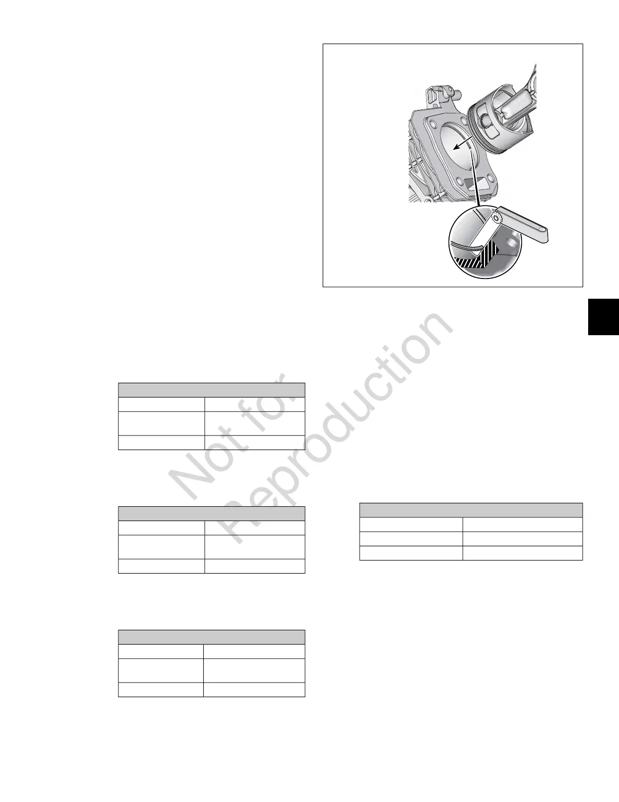
B. See Figure 62. Insert ring approximately one inch
(25.4 mm) into cylinder bore.
C. Square ring in the bore using the top of the piston.
D. Measure the ring end gap with a feeler gauge.
E. Do not use the top compression ring if the end gap
is at the reject size shown below.
Top Compression Ring End Gap
Reject SizeModels
0.040 in (1.01 mm) or more130G00, 131G00,
13R200
0.037 in (0.94 mm) or more13U100, 13U200
F. Repeat steps 1(B) thru 1(D) using new middle oil
wiper ring. Do not use the ring if the end gap is at
the reject size shown below.
Middle Oil Wiper Ring End Gap
Reject SizeModels
0.044 in (1.11 mm) or more130G00, 131G00,
13R200
0.047 in (1.19 mm) or more13U100, 13U200
G. Repeat steps 1(B) thru 1(D) using rails of new oil
control ring. Do not use the ring if the end gaps are
at the reject size shown below.
Oil Control Ring End Gap
Reject SizeModels
0.055 in (1.39 mm) or more130G00, 131G00,
13R200
0.053 in (1.34 mm) or more13U100, 13U200
62
Connecting Rod
1. Inspect the connecting rod for cracks, twisting or
bending.
2. Inspect bearing surfaces for scratches or scoring.
3. Inspect dipper on connecting rod cap for bending,
chipping, or cracking.
NOTE: Replace connecting rod and cap if any of the
above conditions are found. Always replace connecting
rod and cap as an assembly.
4. Start two hex flange screws to fasten connecting rod
cap to connecting rod. Alternately tighten screws as
follows.
Connecting Rod Cap Screws
TorqueModels
110-140 lb-in (12.4-15.8 N-m)130G00, 131G00, 13R200
124-142 lb-in (14-16 N-m)13U100, 13U200
NOTE: Install connecting rod cap, so that match marks
on connecting rod cap and shank are aligned.
5. Obtain Telescoping Gauge (Part No. 19485) and inside
micrometer or plug gauge.
6. See A of Figure 63. Measure piston pin bearing bore
diameter at two locations- parallel and perpendicular
to the crankshaft. Replace connecting rod if either
measurement is 0.711 inches (18.06 mm) or more.
7. See B of Figure 63. Measure the crank pin bearing bore
diameter at two locations- parallel and perpendicular
to the crankshaft. Replace the connecting rod if either
measurement is at the reject size shown below.
55
6
 Loading...