INSTALL EXTERNAL ASSEMBLIES
Armature
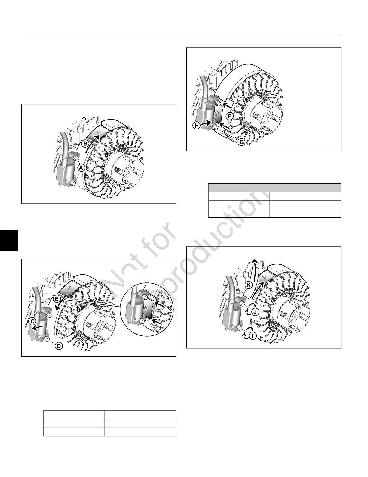
1. See Figure 105. Loosely install two hex flange screws
(A) to fasten armature to crankcase.
2. Rotate flywheel to move magnet away from armature
legs (B).
105
3. See Figure 106. Slide armature (C) away from flywheel.
4. Tighten bottom hex flange screw (D) until snug.
5. Rotate flywheel, so that magnet is aligned with armature
legs (E).
106
6. See Figure 107. Insert feeler gauge (F) or Armature Air
Gap Gauge (Part No. CE5121) between flywheel and
armature legs. Loosen bottom hex flange screw (G)
and push armature legs (H) tight against gauge to set
air gap as follows.
Armature Air GapModels
0.010-0.014 in (0.25-0.35 mm)130G00, 131G00, 13R200
0.008-0.016 in (0.20-0.40 mm)13U100, 13U200
107
7. See Figure 108. Tighten bottom hex flange screw (I)
and then top hex flange screw (J) as follows.
Armature Screws
TorqueModels
80-110 lb-in (9-12.4 N-m)130G00, 131G00, 13R200
71-124 lb-in (8-14 N-m)13U100, 13U200
8. Rotate flywheel to remove gauge (K).
108
9. See Figure 109. Route remote magneto stop terminal
wire between ribs at top of crankcase. First pull wire
tight and then push down firmly, so that it is snugly
seated against casting. Capture wire in clip on flywheel
guard.
NOTE: Through contact with governor lever, link, or
springs, loose wires can interfere with governor
operation.
76
8
 Loading...