6-5
Optional Accessories
6
Paper Feeder
NOTE
Load paper in the paper feeder in the same manner as you load paper in Cassette 1. For
more details, see "Chapter 2 Loading and Outputting Paper".
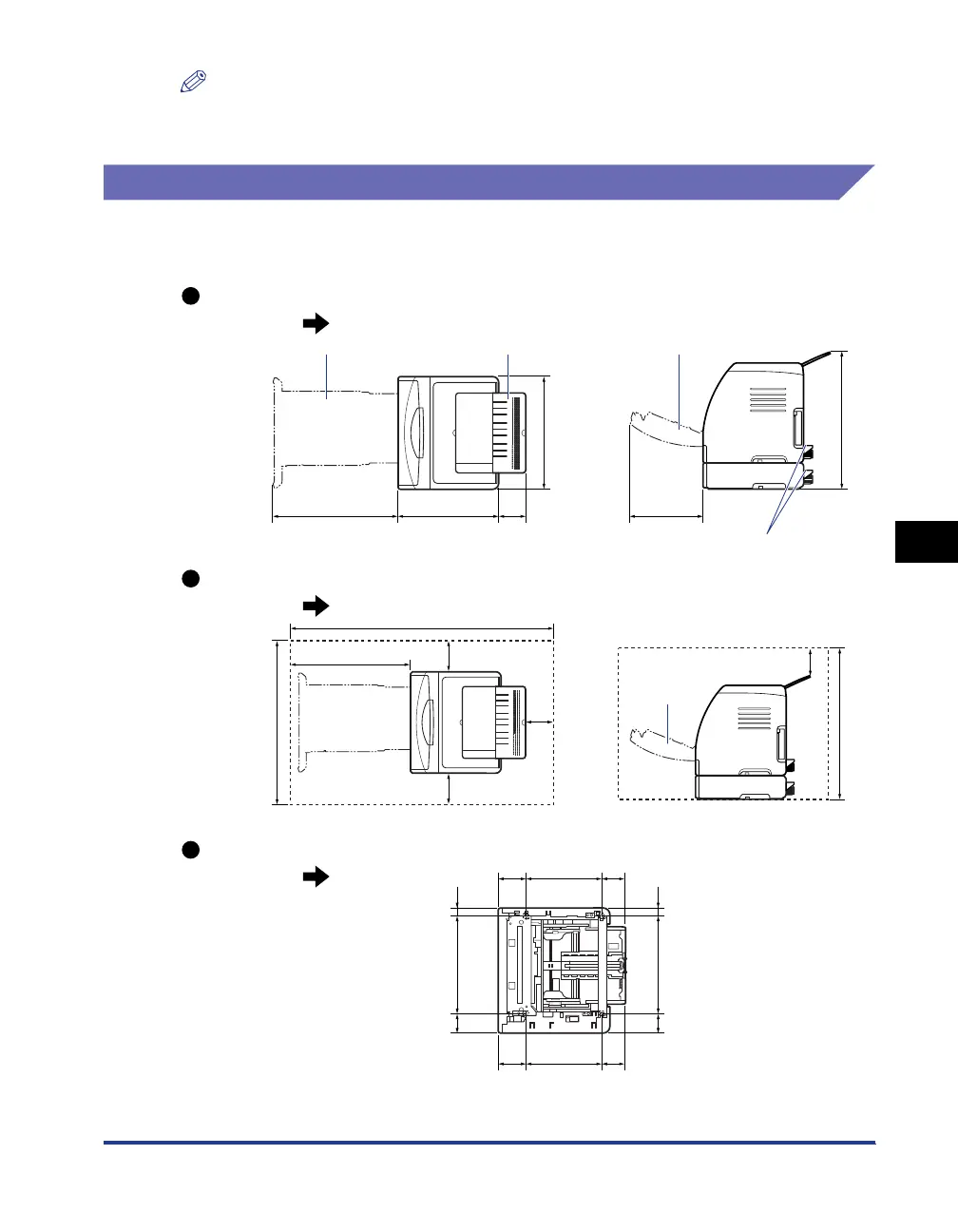
Installation Space
The dimensions of each part, foot positions, and the space required for using the
printer with the paper feeder installed are indicated in the following figures:
Front Surface
Front Surface
Front Surface
Required Peripheral Space
Dimensions of the Printer
Foot Positions of the Paper Feeder
Paper cassette Output tray Front cover
Cassette protective cover
The right feet are 3.1 mm high and their top surface is 17.3 mm square.
The left feet are 2.5 mm high and their top surface is 17.3 mm square.
400 365 107 272
407
514
(mm)
Paper cassette
Front cover
228
176
11.5 11.5
600
1300
(mm)
430
690
239.295.7 73.6
239.282.5 86.8
316.859.7 30.5
316.859.7 30.5
(mm)
 Loading...