RM23712 TPS
54
Figure 31.3.5''HDD Removal
NOTE: Due to degraded performance and reliability concerns, the use of the 3.5” drive blank as a
2.5” device bracket is intended to support SSD type storage devices only. Installing a 2.5” hard
disk drive into the 3.5” drive blank cannot be supported.
Each drive carrier includes separate LED indicators for drive Activity and drive Status. Light pipes
integrated into the drive carrier assembly direct light emitted from LEDs mounted next to each drive
connector on the backplane to the drive carrier faceplate, making them visible from the front of the
system.
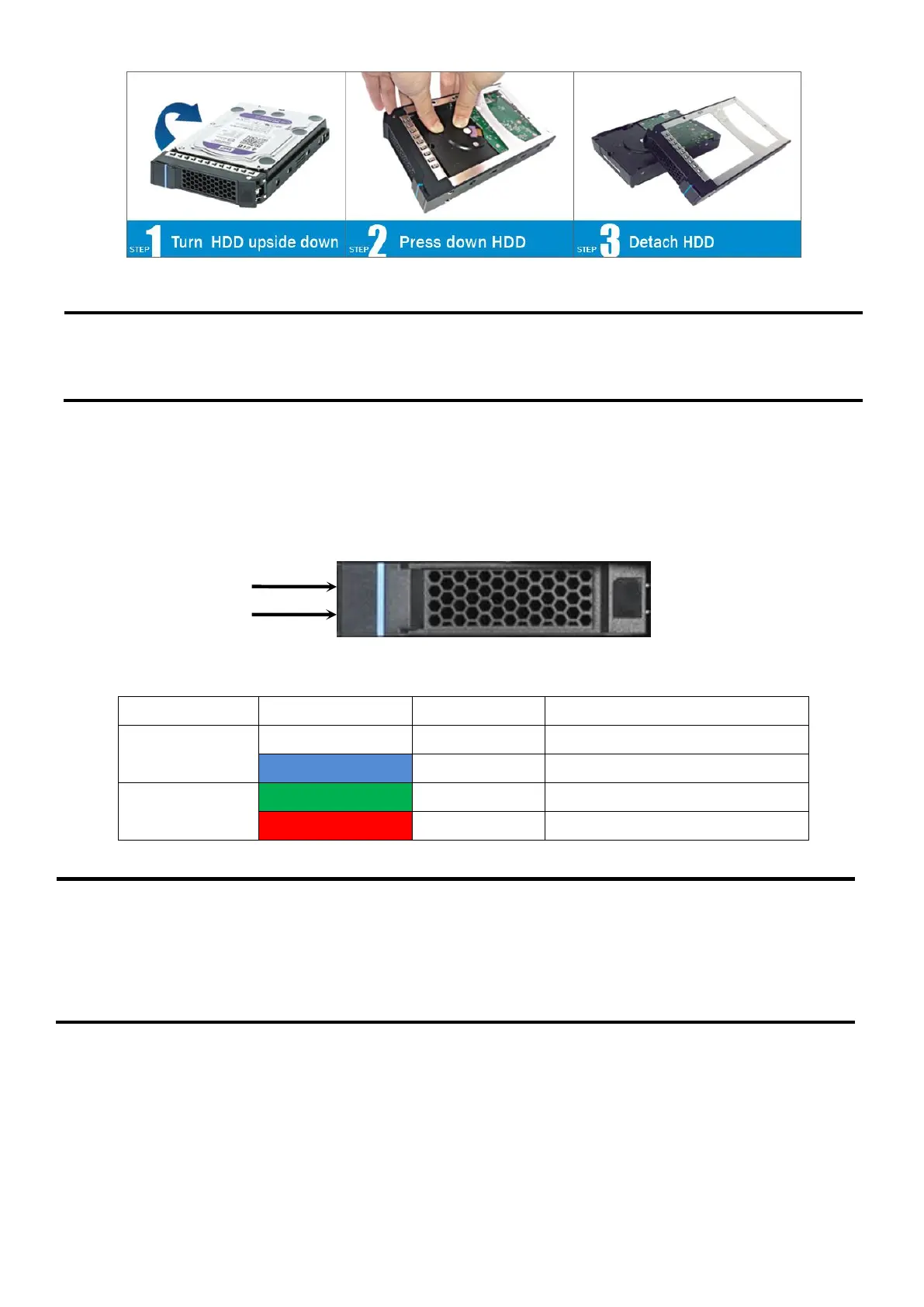
Figure 32. Drive Tray LED Identification
Table 42 Drive Power LED/Activity LED States
Hard drive fault has occurred
5.4 Peripheral Power Sources
Power for all backplanes and peripheral storage devices is drawn from two power connectors
labeled as “HSBP_PWR” and the “Peripheral PWR” on the server board as illustrated below.
Blue power LED
Green Activity LED
2.5''/3.5'' drive tray
NOTE: The drive activity LED is driven by signals coming from the drive itself. Drive vendors may
choose to operate the activity LED different from what is described in the table above. Should the
activity LED on a given drive type behave differently than what is described, customers should
reference the drive vendor specifications for the specific drive model to determine what the
expected drive activity LED operation should be.
 Loading...