RM23712 TPS
70
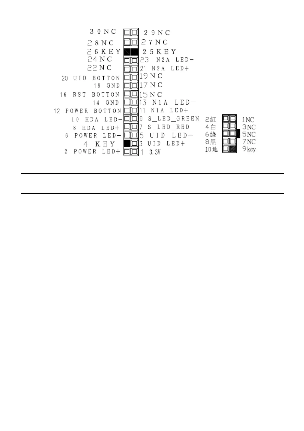
Figure 46.LED Connectors Pin-out
The BMC-detected states are included in the LED states. For fault states that are monitored by the
BMC sensors, the contribution to the LED state follows the associated sensor state, with priority
given to the most critical asserted state.
When the server is powered down (transitions to the DC-off state ), the BMC is still on standby
power and retains the sensor and front panel status LED state established before the power-down
event.
When AC power is first applied to the system, the status LED turns solid blue and then immediately
changes to extinguish to indicate that the power is failure.
NOTE: The Status LED is controlled by the BMC but the BIOS informs the BMC of the state to
which the Status LED should be set.
 Loading...